Content .. 1505 1506 1507 1508 ..
Dodge Ram Truck 1500-2500-3500. Manual - part 1507
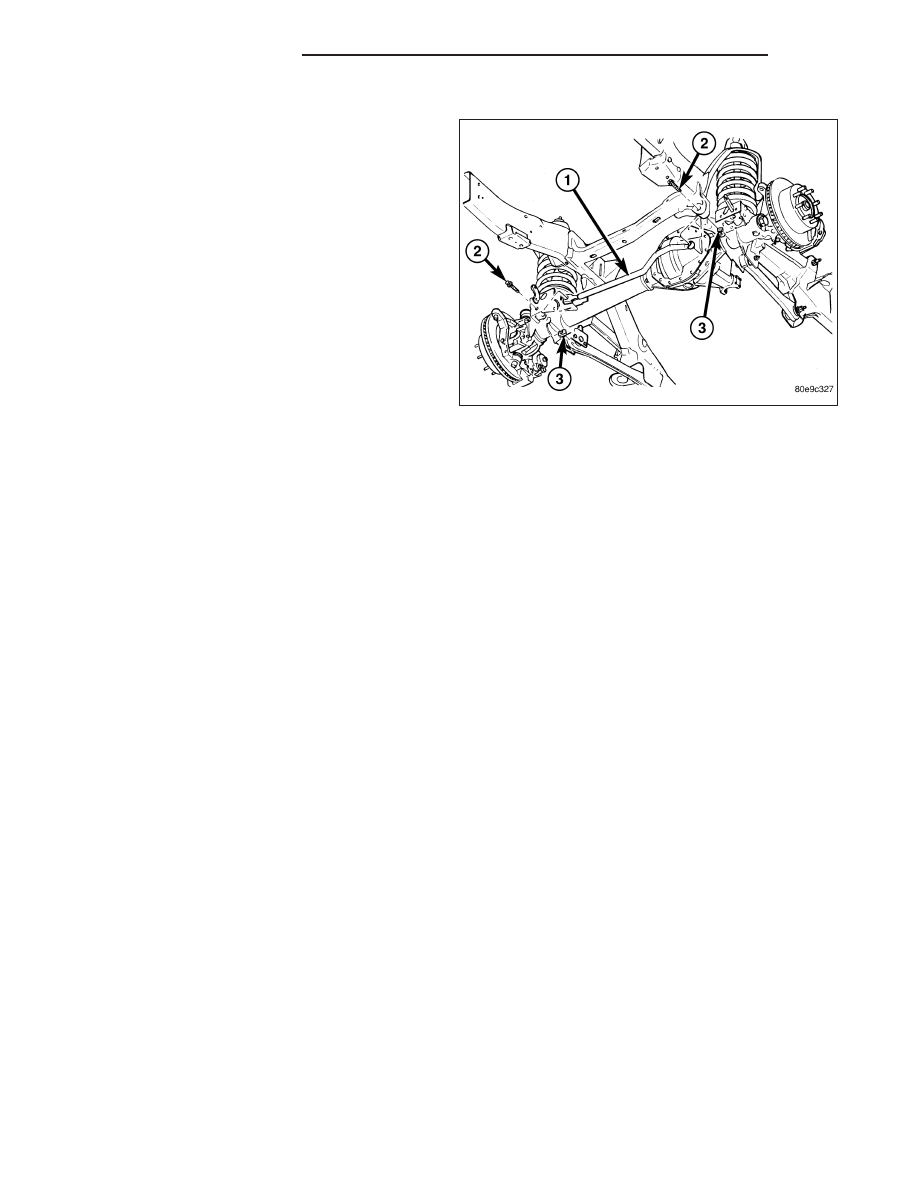
INSTALLATION
1. Install the track bar (1).
2. Install the new bolts (2) and nuts (3). Tighten to
203 N·m (150 ft lbs.).
3. Remove the supports under the axle and lower the
vehicle to the ground.
19 - 62
LINKAGE - LINK/COIL
DR/DH