Dodge Ram Truck 1500-2500-3500. Manual - part 1441


  Index      Dodge     Dodge Ram Truck 1500-2500-3500 - service repair manual 2005 year


Search            


Content   ..  1439  1440  1441  1442   ..


Dodge Ram Truck 1500-2500-3500. Manual - part 1441
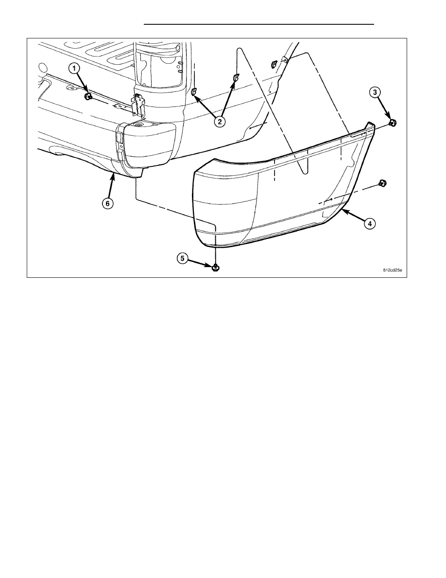


4. Position the end caps (3) over the support brackets (1) and install.

5. Install the screws (2 and 4).

FRAME

WARNING

WARNINGS

Use eye protection when grinding or welding metal. Failure to do this could result in serious personal injury
or death.

Before proceeding with frame repair involving grinding or welding, verify that the vehicle fuel system is not
leaking or in contact with the repair area. Failure to do this could result in serious personal injury or death.

Do not allow an open flame or heat and metal spatter from arc welding to contact plastic body panels. Fire,
explosion can result causing serious personal injury or death.

When welded frame components are replaced, ensure that a complete penetration weld is achieved during
installation. If not, dangerous operating conditions can result.

Stand clear of cables or chains on pulling equipment during frame straightening operations. Failure to do
this can result in serious personal injury or death.

Do not venture under a hoisted vehicle that is not supported on safety stands. Walking under an unsup-
ported vehicle can result in serious personal injury or death.

1500 series Dodge Ram Trucks (2002 and later) are not designed for snow plow equipment. The front col-
lision repair tips must not be installed on any truck equipped with a snow plow, or even intended to be
equipped with a snow plow.

13 - 14

FRAME & BUMPERS

DR/DH

Do not reuse damaged fasteners. The quality of repair would be suspect. Failure to use only production
fasteners or fasteners of equivalent hardness can result in loosening or failure of the part. Do not drill any
holes in the frame that are not specifically outlined in this, or in other DaimlerChrysler procedures as frame
rail failure can result causing serious personal injury or death. When using heat to straighten frame com-
ponents, do not exceed 566°C (1050°F). If temperature is exceeded, metal fatigue can happen and result in
serious personal injury or death.

STANDARD PROCEDURE

LIGHT DUTY FRONT FRAME RAIL TIP REPLACEMENT

CAUTION: This procedure is designed to replace the front frame rail tips that have been damaged in the
crush initiator zones. Prior to any cutting, the vehicle must be mounted on the appropriate frame repair
equipment (“frame rack”), checked with three dimensional measuring equipment, and the necessary pull
corrections made. If damage remains in the frame beyond the area covered by this service part after the
pull, the frame must be replaced in its entirety.

CAUTION: Inspect the tire winch assembly for damage. If any one or more of the following are evident,
replace the winch assembly.

Indications of cracked or bulging plastic.

Housing flanges are bent or cracked.

If winch was loose before repair.

If the rivet heads are separated from the housing in any way.

NOTE: Procedures for 4X2 and 4X4 are common except as noted in this procedure.

1. Before proceeding with this repair procedure review

the required service warnings and precautions.
(Refer to 13 - FRAME & BUMPERS/FRAME -
WARNING)

2. Disconnect and isolate the battery negative cable.

3. Remove the front wheelhouse splash shield. (Refer

to 23 - BODY/EXTERIOR/FRONT WHEELHOUSE
SPLASH SHIELD - REMOVAL)

4. Remove the bolts and position aside the wire har-

ness and grounds, if required.

5. Remove the front bumper. (Refer to 13 - FRAME &

BUMPERS/BUMPERS/FRONT

BUMPER

-

REMOVAL)

6. Loosen and lower the stabilizer bar mount and bar.

(Refer to 2 - SUSPENSION/FRONT/STABILIZER
BAR - REMOVAL)

7. Remove the front cab mount bolt (6) to the Front End Sheet Metal (FESM) bracket.

DR/DH

FRAME & BUMPERS

13 - 15

8. Make a vertical mark (6) on the inside and outside

face of the frame rail 112 mm (4.5 in.) from the for-
ward edge of the PLP hole (3) in the sides of the
rail.

9. Using a straightedge, connect the two lines on the

top and bottom of the rail.

10. Using the service tip as a guide, recheck your cut

lines to ensure the service tip will fit when the cut
is made.

CAUTION: Do not use any flame or plasma cutting
equipment to cut the frame in this procedure. This
is due to the inaccurate nature of the cut-line and
the fact that the high temperatures achieved dur-
ing flame or plasma cutting will change the metal
characteristics and may weaken the frame and/or
repair location.

11. Using a reciprocating saw or equivalent, carefully cut and remove the damaged frame rail tip (7).

12. Assemble the service sleeve. Refer to SERVICE

SLEEVE ASSEMBLY at the end of this procedure.

NOTE: Any burned surface coatings will need to
be removed from the sleeve prior to installation
and application of corrosion preventative coatings.

13. Smooth and square the cut edges of the original

frame.

14. Dress the cut edge of the existing frame in prep-

aration for the new rail tip.

15. Drill four 13 mm (0.5 in.) diameter holes (9) in the

new tip (1) and four more in the existing frame (2)
to accommodate ring-fillet welds. Center these
holes (8) 19 mm (0.75 in.) from the cut face of the
rail and (6) 38 mm (1.5 in.) from the top and bot-
tom of the rail.

13 - 16

FRAME & BUMPERS

DR/DH

16. Bevel the edges of the new tip, existing frame,

and ring-fillet holes 25° - 30° (3). Scribing a line 2
mm from the cut edge and then grinding back to
the mark will simplify the bevel creation process
and accuracy.

17. Remove any burrs at the holes and beveled

edges.

18. Dry fit the new rail to ensure alignment and fit and

make any adjustments as necessary.

19. Remove all internal and external OEM e-coat

within 51 mm (2.0 in.) of the weld joint on the
replacement tip and the existing frame rail.

NOTE: Any burned surface coatings will need to
be removed prior to application of corrosion pre-
ventative coatings.

CAUTION: Shield the surrounding area and com-
ponents from exposure to the welding spatter and
heat.

20. On 4X4 models use the service sleeve (3) as a

template to drill a hole in the frame tip (1) to
accommodate the sway bar mounting bolt (6).

DR/DH

FRAME & BUMPERS

13 - 17


Content   ..  1439  1440  1441  1442   ..