Dodge Ram Truck 1500-2500-3500. Manual - part 1340


  Index      Dodge     Dodge Ram Truck 1500-2500-3500 - service repair manual 2005 year


Search            


Content   ..  1338  1339  1340  1341   ..


Dodge Ram Truck 1500-2500-3500. Manual - part 1340
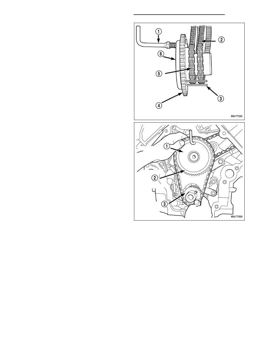


7. Install

both

secondary

chains

onto

the

idler

sprocket. Align two plated links on the secondary
chains to be visible through the two lower openings
on the idler sprocket (4 o’clock and 8 o’clock).
Once the secondary timing chains are installed,
position special tool 8515 (6) to hold chains in
place for installation.

8. Align primary chain double plated links with the tim-

ing mark at 12 o’clock (1) on the idler sprocket.
Align the primary chain single plated link with the
timing mark at 6 o’clock on the crankshaft sprocket
(3).

9. Lubricate idler shaft and bushings with clean

engine oil.

10. Install all chains, crankshaft sprocket, and idler

sprocket as an assembly. After guiding both sec-
ondary chains through the block and cylinder
head openings, affix chains with a elastic strap or
the equivalent, This will maintain tension on
chains to aid in installation.

NOTE: It will be necessary to slightly rotate cam-
shafts for sprocket installation.

11. Align left camshaft sprocket “L” dot to plated link

on chain.

12. Align right camshaft sprocket “R” dot to plated link

on chain.

CAUTION: Remove excess oil from the camshaft
sprocket bolt. Failure to do so can result in over-torque of bolt resulting in bolt failure.

13. Remove Special Tool 8515, then attach both sprockets to camshafts. Remove excess oil from bolts, then Install

sprocket bolts, but do not tighten at this time.

14. Verify that all plated links are aligned with the marks on all sprockets and the “V8” marks on camshaft sprockets

are at the 12 o’clock position.

CAUTION: Ensure the plate between the left secondary chain tensioner and block is correctly installed.

15. Install both secondary chain tensioners. Tighten bolts to 28 N·m (250 in. lbs.).

NOTE: Left and right secondary chain tensioners are not common.

16. Before installing idler sprocket bolt, lubricate washer with oil, and tighten idler sprocket assembly retaining bolt

to 34 N·m (25 ft. lbs.).

17. Remove all locking pins (3) from tensioners.

CAUTION: After pulling locking pins out of each tensioner, DO NOT manually extend the tensioner(s)
ratchet. Doing so will over tension the chains, resulting in noise and/or high timing chain loads.

9 - 2282

ENGINE - 4.7L - SERVICE INFORMATION

DR/DH

18. Using Special Tool 6958, Spanner with Adaptor

Pins 8346, tighten left (3) and right (4), camshaft
sprocket bolts to 122 N·m (90 ft. lbs.).

19. Rotate engine two full revolutions. Verify timing

marks are at the follow locations:

primary chain idler sprocket dot is at 12 o’clock

primary chain crankshaft sprocket dot is at 6
o’clock

secondary chain camshaft sprockets “V8” marks
are at 12 o’clock

20. Lubricate all three chains with engine oil.

21. After installing all chains, it is recommended that

the idler gear (1) end play be checked. The end
play must be within 0.10–0.25 mm (0.004–0.010
in.). If not within specification, the idler gear must
be replaced.

22. Install timing chain cover (Refer to 9 - ENGINE/

VALVE TIMING/TIMING BELT / CHAIN COV-
ER(S) - INSTALLATION) and crankshaft damper
(Refer to 9 - ENGINE/ENGINE BLOCK/VIBRA-
TION DAMPER - INSTALLATION).

23. Install cylinder head covers (Refer to 9 - ENGINE/

CYLINDER HEAD/CYLINDER HEAD COVER(S) -
INSTALLATION).

NOTE: Before installing threaded plug in right cyl-
inder head, the plug must be coated with sealant
to prevent leaks.

24. Coat the large threaded access plug with Mopar

T

Thread Sealant with Teflon, then install into the
right cylinder head and tighten to 81 N·m (60 ft.
lbs.).

25. Install the oil fill housing.

26. Install access plug in left cylinder head.

DR/DH

ENGINE - 4.7L - SERVICE INFORMATION

9 - 2283

27. Install power steering pump (Refer to 19 - STEERING/PUMP - INSTALLATION).

28. Install radiator fan shroud.

29. Fill cooling system (Refer to 7 - COOLING - STANDARD PROCEDURE).

30. Connect negative cable to battery.

SHAFT - IDLER

REMOVAL

1. Remove the primary and secondary timing chains and sprockets (Refer to 9 - ENGINE/VALVE TIMING/TIMING

BELT/CHAIN AND SPROCKETS - REMOVAL) .

NOTE: To remove the idler shaft, it is necessary to tap threads into the shaft, to install the removal tool.

2. Using a 12 mm X 1.75 tap, cut threads in the idler shaft center bore.

3. Cover the radiator core with a suitable cover.

CAUTION: Use care when removing the idler shaft, Do not strike the radiator cooling fins with the slide
hammer.

4. Using Special Tool 8517 Slide Hammer, remove the idler shaft.

INSTALLATION

1. Thoroughly clean the idler shaft bore.

2. Position the idler shaft in the bore.

NOTE: The two lubrication holes in the idler shaft do not require any special alignment.

NOTE: Before using the retaining bolt to install the idler shaft, coat the threads and the pilot on the idler
shaft, with clean engine oil.

3. Using the primary idler sprocket retaining bolt and washer, carefully draw the idler shaft into the bore until fully

seated.

4. Coat the idler shaft with clean engine oil.

5. Install the timing chains and sprockets (Refer to 9 - ENGINE/VALVE TIMING/TIMING BELT/CHAIN AND

SPROCKETS - INSTALLATION) .

9 - 2284

ENGINE - 4.7L - SERVICE INFORMATION

DR/DH

ENGINE - 5.7L - SERVICE INFORMATION

TABLE OF CONTENTS

page

page

ENGINE - 5.7L - SERVICE INFORMATION

DESCRIPTION

. . . . . . . . . . . . . . . . . . . . . . . 2287

DIAGNOSIS AND TESTING

DIAGNOSIS AND TESTING - ENGINE

DIAGNOSIS - INTRODUCTION . . . . . . . . . . 2288

DIAGNOSIS AND TESTING - ENGINE

DIAGNOSIS - PERFORMANCE . . . . . . . . . 2288

DIAGNOSIS AND TESTING - ENGINE

DIAGNOSIS - MECHANICAL . . . . . . . . . . . 2290

DIAGNOSIS AND TESTING - CYLINDER

COMPRESSION PRESSURE . . . . . . . . . . . 2290

DIAGNOSIS AND TESTING - CYLINDER

COMBUSTION PRESSURE LEAKAGE . . . . 2291

DIAGNOSIS AND TESTING - ENGINE

DIAGNOSIS - LUBRICATION . . . . . . . . . . . 2292

DIAGNOSIS AND TESTING - ENGINE

DIAGNOSIS - MECHANICAL . . . . . . . . . . . 2293

STANDARD PROCEDURE

STANDARD PROCEDURE - REPAIR

DAMAGED OR WORN THREADS . . . . . . . 2295

STANDARD PROCEDURE—HYDROSTATIC

LOCK . . . . . . . . . . . . . . . . . . . . . . . . . . . . . 2295

REMOVAL

. . . . . . . . . . . . . . . . . . . . . . . . . . . 2296

INSTALLATION

. . . . . . . . . . . . . . . . . . . . . . . 2301

SPECIFICATIONS

5.7L ENGINE

. . . . . . . . . . . . . . . . . . . . . . . 2306

TORQUE

. . . . . . . . . . . . . . . . . . . . . . . . . . 2312

SPECIAL TOOLS

5.7L ENGINE

. . . . . . . . . . . . . . . . . . . . . . . 2314

ELEMENT - AIR CLEANER

REMOVAL

. . . . . . . . . . . . . . . . . . . . . . . . . . . 2318

INSTALLATION

. . . . . . . . . . . . . . . . . . . . . . . 2319

CYLINDER HEAD

OPERATION—CYLINDER HEAD

. . . . . . . . . . 2320

DIAGNOSIS AND TESTING—CYLINDER HEAD

GASKET FAILURE

. . . . . . . . . . . . . . . . . . . 2320

REMOVAL

. . . . . . . . . . . . . . . . . . . . . . . . . . . 2321

CLEANING

. . . . . . . . . . . . . . . . . . . . . . . . . . 2323

INSPECTION

. . . . . . . . . . . . . . . . . . . . . . . . . 2323

INSTALLATION

. . . . . . . . . . . . . . . . . . . . . . . 2324

COVER - CYLINDER HEAD

REMOVAL

. . . . . . . . . . . . . . . . . . . . . . . . . . . 2328

INSTALLATION

. . . . . . . . . . . . . . . . . . . . . . . 2331

VALVES & SEATS - INTAKE/EXHAUST

DESCRIPTION

DESCRIPTION - VALVE GUIDES

. . . . . . . . 2333

DESCRIPTION

. . . . . . . . . . . . . . . . . . . . . . 2333

STANDARD PROCEDURE - REFACING

. . . . 2333

REMOVAL

. . . . . . . . . . . . . . . . . . . . . . . . . . . 2334

INSTALLATION

. . . . . . . . . . . . . . . . . . . . . . . 2334

ROCKER ARM

REMOVAL

. . . . . . . . . . . . . . . . . . . . . . . . . . . 2335

INSTALLATION

. . . . . . . . . . . . . . . . . . . . . . . 2337

SEALS - VALVE GUIDE

DESCRIPTION

. . . . . . . . . . . . . . . . . . . . . . . 2339

SPRINGS - VALVE

REMOVAL

. . . . . . . . . . . . . . . . . . . . . . . . . . . 2339

INSTALLATION

. . . . . . . . . . . . . . . . . . . . . . . 2345

ENGINE BLOCK

CLEANING

. . . . . . . . . . . . . . . . . . . . . . . . . . 2349

INSPECTION

. . . . . . . . . . . . . . . . . . . . . . . . . 2350

CAMSHAFT

REMOVAL

REMOVAL - CAMSHAFT CORE

HOLE PLUG . . . . . . . . . . . . . . . . . . . . . . . . 2350

REMOVAL - CAMSHAFT

. . . . . . . . . . . . . . 2351

INSPECTION

. . . . . . . . . . . . . . . . . . . . . . . . . 2355

INSTALLATION

INSTALLATION - CAMSHAFT CORE HOLE

PLUG . . . . . . . . . . . . . . . . . . . . . . . . . . . . . 2356

INSTALLATION - CAMSHAFT

. . . . . . . . . . . 2356

CRANKSHAFT

REMOVAL

. . . . . . . . . . . . . . . . . . . . . . . . . . . 2363

INSTALLATION

. . . . . . . . . . . . . . . . . . . . . . . 2367

BEARINGS - CRANKSHAFT MAIN

STANDARD PROCEDURE - CRANKSHAFT

MAIN BEARING - FITTING

. . . . . . . . . . . . . 2372

INSPECTION

. . . . . . . . . . . . . . . . . . . . . . . . . 2372

SEAL - CRANKSHAFT OIL - FRONT

REMOVAL

. . . . . . . . . . . . . . . . . . . . . . . . . . . 2373

INSTALLATION

. . . . . . . . . . . . . . . . . . . . . . . 2374

SEAL - CRANKSHAFT OIL - REAR

DIAGNOSIS AND TESTING - REAR SEAL

AREA LEAKS

. . . . . . . . . . . . . . . . . . . . . . . 2374

REMOVAL

. . . . . . . . . . . . . . . . . . . . . . . . . . . 2375

INSTALLATION

. . . . . . . . . . . . . . . . . . . . . . . 2376

RETAINER - CRANK REAR OIL - SEAL

REMOVAL

. . . . . . . . . . . . . . . . . . . . . . . . . . . 2376

INSTALLATION

. . . . . . . . . . . . . . . . . . . . . . . 2377

FLEX PLATE

REMOVAL

. . . . . . . . . . . . . . . . . . . . . . . . . . . 2377

INSTALLATION

. . . . . . . . . . . . . . . . . . . . . . . 2378

TAPPETS - HYDRAULIC ROLLER

DIAGNOSIS AND TESTING - HYDRAULIC

TAPPETS

. . . . . . . . . . . . . . . . . . . . . . . . . . 2378

REMOVAL

. . . . . . . . . . . . . . . . . . . . . . . . . . . 2379

INSTALLATION

. . . . . . . . . . . . . . . . . . . . . . . 2380

PISTON & CONNECTING ROD

DESCRIPTION

. . . . . . . . . . . . . . . . . . . . . . . 2380

STANDARD PROCEDURE -

PISTON FITTING

. . . . . . . . . . . . . . . . . . . . 2381

DR/DH

ENGINE - 5.7L - SERVICE INFORMATION

9 - 2285


Content   ..  1338  1339  1340  1341   ..