Dodge Ram Truck 1500-2500-3500. Manual - part 1290


  Index      Dodge     Dodge Ram Truck 1500-2500-3500 - service repair manual 2005 year


Search            


Content   ..  1288  1289  1290  1291   ..


Dodge Ram Truck 1500-2500-3500. Manual - part 1290


8. Rocker arm ears contacting valve spring retainer.

9. Rocker arm loose, adjuster stuck or at maximum extension and still leaves lash in the system.

10. Oil leak or excessive cam bore wear in cylinder head.

11. Faulty lash adjuster.

a. Check lash adjusters for sponginess while installed in cylinder head and cam on camshaft at base circle.
Depress part of rocker arm over adjuster. Normal adjusters should feel firm when pressed quickly. When pressed
very slowly, lash adjusters should collapse.

b. Remove suspected lash adjusters, and replace.

c. Before installation, make sure adjusters are full of oil. This can be verified by little plunger travel when lash
adjuster is depressed quickly.

REMOVAL

1. Disconnect battery negative cable.

2. Raise the vehicle on a hoist.

3. Disconnect the exhaust pipe at the right side

exhaust manifold.

4. Drain the engine coolant (Refer to 7 - COOLING -

STANDARD PROCEDURE).

5. Lower the vehicle.

6. Remove the intake manifold (Refer to 9 - ENGINE/

MANIFOLDS/INTAKE MANIFOLD - REMOVAL).

7. Remove the cylinder head cover (Refer to 9 -

ENGINE/CYLINDER HEAD - REMOVAL).

8. Remove the fan shroud (Refer to 7 - COOLING/

ENGINE/RADIATOR FAN - REMOVAL).

9. Remove oil fill housing from cylinder head.

10. Remove accessory drive belt (Refer to 7 - COOL-

ING/ACCESSORY

DRIVE/DRIVE

BELTS

-

REMOVAL).

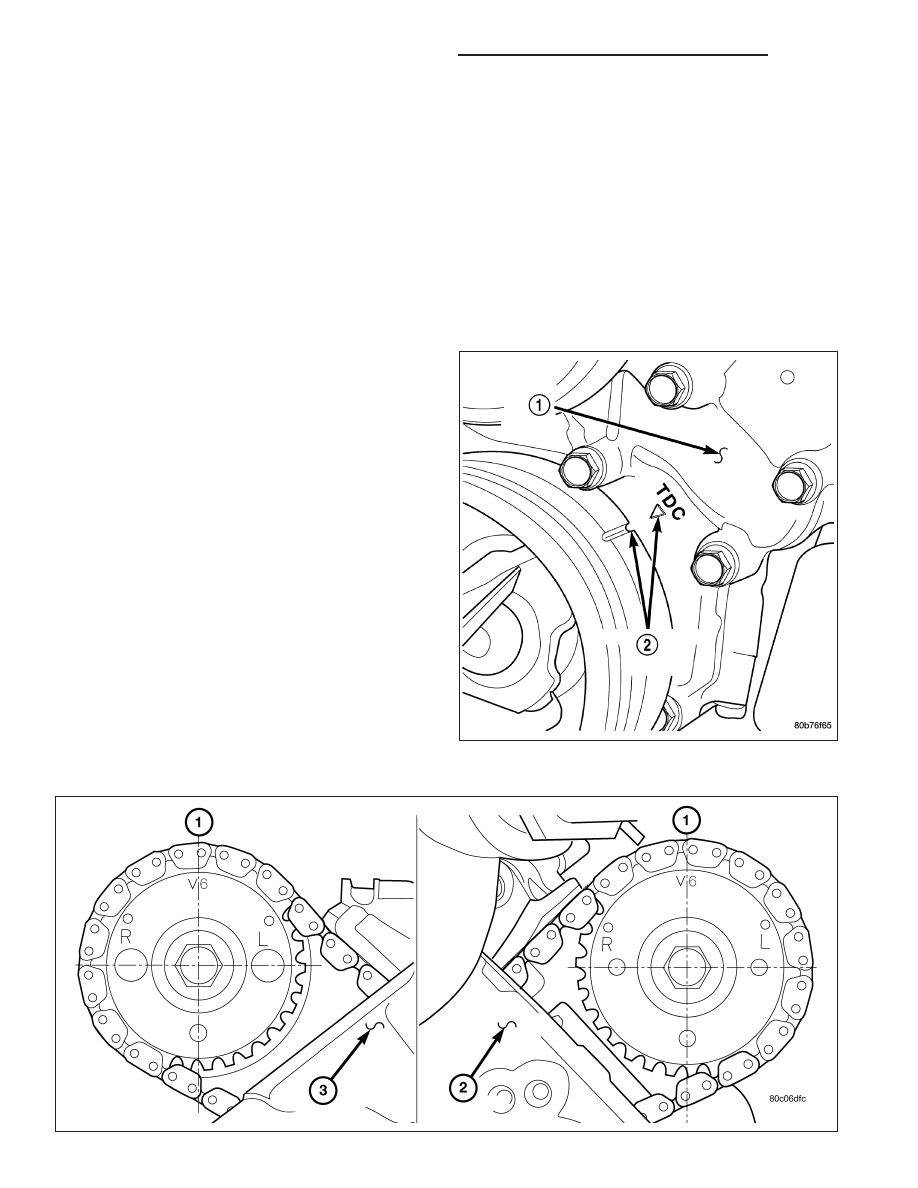
11. Rotate the crankshaft until the damper timing

mark is aligned with TDC indicator mark (2).

9 - 2082

ENGINE - 3.7L - SERVICE INFORMATION

DR/DH

12. Verify the V6 mark on the camshaft sprocket is at the 12 o’clock position. Rotate the crankshaft one turn if

necessary.

13. Remove the crankshaft damper (Refer to 9 - ENGINE/ENGINE BLOCK/VIBRATION DAMPER - REMOVAL).

14. Remove the timing chain cover (Refer to 9 - ENGINE/VALVE TIMING/TIMING BELT / CHAIN COVER(S) -

REMOVAL).

15. Lock the secondary timing chains to the idler

sprocket using Special Tool 8429 Timing Chain
Holding Fixture (1).

NOTE: Mark the secondary timing chain prior to
removal to aid in installation.

16. Mark the secondary timing chain, one link on

each side of the V6 mark on the camshaft drive
gear.

17. Remove the right side secondary chain tensioner

(Refer to 9 - ENGINE/VALVE TIMING/TIMING
BELT/CHAIN AND SPROCKETS - REMOVAL).

18. Remove the cylinder head access plug (1,2).

19. Remove the right side secondary chain guide

(Refer to 9 - ENGINE/VALVE TIMING/TIMING
BELT/CHAIN AND SPROCKETS - REMOVAL).

CAUTION: The nut on the right side camshaft
sprocket should not be removed for any reason,
as the sprocket and camshaft sensor target wheel
is serviced as an assembly. If the nut was
removed, torque nut to 5 N·m (44 in. lbs.).

20. Remove the retaining bolt and the camshaft drive

gear.

CAUTION: Do not allow the engine to rotate.
severe damage to the valve train can occur.

CAUTION: Do not overlook the four smaller bolts at the front of the cylinder head. Do not attempt to remove
the cylinder head without removing these four bolts.

CAUTION: Do not hold or pry on the camshaft target wheel for any reason. A damaged target wheel can
result in a vehicle no start condition.

DR/DH

ENGINE - 3.7L - SERVICE INFORMATION

9 - 2083

NOTE: The cylinder head is attached to the cylin-
der block with twelve bolts.

21. Remove the cylinder head retaining bolts.

22. Remove the cylinder head and gasket. Discard

the gasket.

CAUTION: Do not lay the cylinder head on its gas-
ket sealing surface, do to the design of the cylin-
der head gasket any distortion to the cylinder
head sealing surface may prevent the gasket from
properly sealing resulting in leaks.

INSTALLATION

NOTE: The cylinder head bolts are tightened using
a torque plus angle procedure. The bolts must be
examined

BEFORE

reuse.

If

the

threads

are

necked down (1) the bolts should be replaced.

Necking can be checked by holding a straight edge
against the threads. If all the threads do not contact
the scale, the bolt should be replaced.

CAUTION: When cleaning cylinder head and cylin-
der block surfaces, DO NOT use a metal scraper
because the surfaces could be cut or ground. Use
only a wooden or plastic scraper (1).

9 - 2084

ENGINE - 3.7L - SERVICE INFORMATION

DR/DH

1. Clean the cylinder head and cylinder block mating surfaces.

2. Position the new cylinder head gasket on the locat-

ing dowels.

CAUTION: When installing cylinder head, use care
not damage the tensioner arm or the guide arm.

3. Position the cylinder head onto the cylinder block.

Make sure the cylinder head seats fully over the
locating dowels.

NOTE: The four M8 cylinder head mounting bolts
(1) require sealant to be added to them before
installing. Failure to do so may cause leaks.

4. Lubricate the cylinder head bolt threads with clean

engine oil and install the eight M10 bolts.

5. Coat the four M8 cylinder head bolts with Mopar

Lock and Seal Adhesive then install the bolts.

NOTE: The cylinder head bolts are tightened using
an angle torque procedure, however, the bolts are
not a torque-to-yield design.

6. Tighten the bolts in sequence using the following

steps and torque values:

Step 1: Tighten bolts 1-8, 27 N·m (20 ft. lbs.).

Step 2: Verify that bolts 1-8, all reached 27 N·m (20 ft. lbs.), by repeating step 1 without loosening the bolts.
Tighten bolts 9 thru 12 to 14 N·m (10 ft. lbs.).

Step 3: Tighten bolts 1-8, 90 °.

Step 4: Tighten bolts 1-8, 90 °, again. Tighten bolts 9-12, 26 N·m (19 ft. lbs.)

DR/DH

ENGINE - 3.7L - SERVICE INFORMATION

9 - 2085


Content   ..  1288  1289  1290  1291   ..