Content .. 1111 1112 1113 1114 ..
Dodge Ram Truck 1500-2500-3500. Manual - part 1113
P0647-HIGH VOLTAGE DETECTED AT THE A/C CLUTCH RELAY (CONTINUED)
3.
FUSED BATTERY SUPPLY
Ignition off.
Disconnect the ECM connectors.
Remove the A/C clutch relay.
NOTE: Check connectors - Clean/repair as necessary.
Ignition on, engine not running.
Measure the voltage on the Fused Battery Supply circuit between the PDC and battery negative.
Is the voltage less than 1 volt?
Yes
>> Go To 4
No
>> Repair the short to voltage.
Perform POWERTRAIN VERIFICATION TEST VER - 1 (DIESEL). (Refer to 8 - ELECTRICAL/ELEC-
TRONIC CONTROL MODULES/ENGINE CONTROL MODULE - DIAGNOSIS AND TESTING)
4.
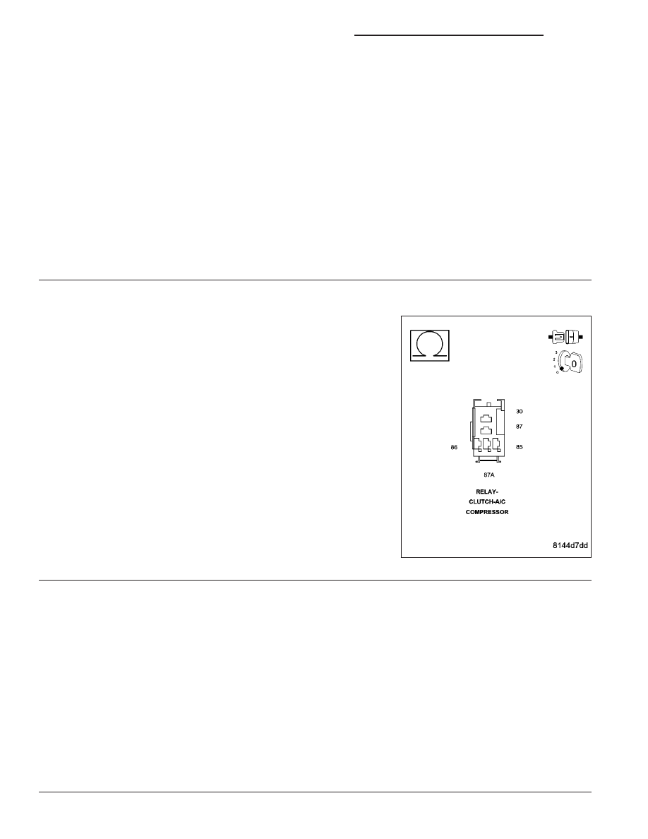
A/C CLUTCH RELAY
Remove the A/C Clutch Relay from the PDC.
NOTE: Check connectors - Clean/repair as necessary.
Measure the resistance between terminals 85 and 86 of the A/C
Clutch Relay.
Is the resistance less than 10 Ohms?
Yes
>> Go To 5
No
>> Replace the A/C clutch relay.
Perform POWERTRAIN VERIFICATION TEST VER - 1
(DIESEL). (Refer to 8 - ELECTRICAL/ELECTRONIC CON-
TROL MODULES/ENGINE CONTROL MODULE - DIAG-
NOSIS AND TESTING)
5.
ECM
Reconnect the ECM harness connectors.
Reinstall the A/C clutch relay.
With the scan tool, actuate the A/C clutch relay.
Turn the ignition on.
While monitoring with the scan tool, disconnect the A/C Clutch Relay from the PDC.
Did DTC P0646 set?
Yes
>> Refer to the INTERMITTENT CONDITION Symptom (Diagnostic Procedure). (Refer to 9 - ENGINE -
DIAGNOSIS AND TESTING)
No
>> Replace the ECM.
Perform POWERTRAIN VERIFICATION TEST VER - 1 (DIESEL). (Refer to 8 - ELECTRICAL/ELEC-
TRONIC CONTROL MODULES/ENGINE CONTROL MODULE - DIAGNOSIS AND TESTING)
9 - 1374
ENGINE - ELECTRICAL DIAGNOSTICS - DIESEL
DR/DH