Content .. 1018 1019 1020 1021 ..
Dodge Ram Truck 1500-2500-3500. Manual - part 1020
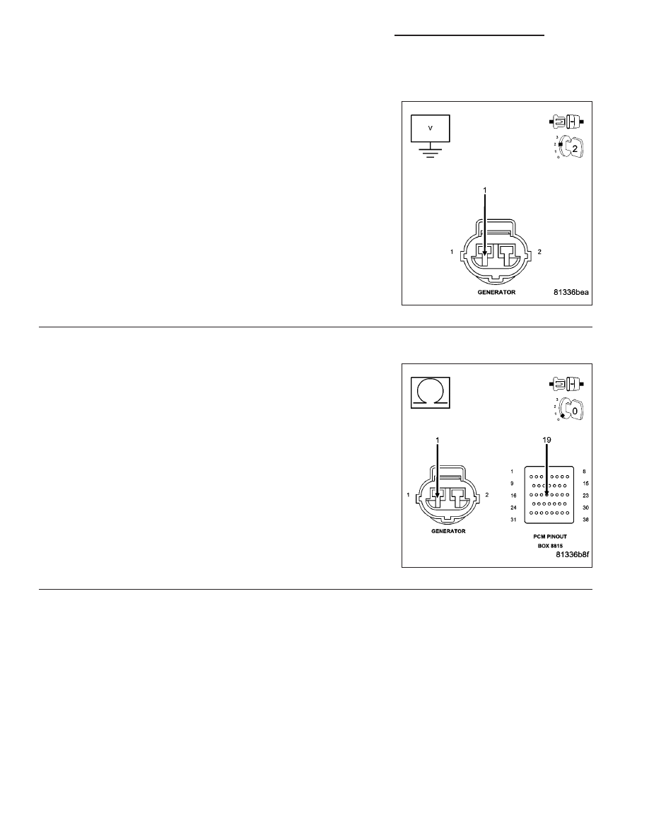
P2503-CHARGING SYSTEM OUTPUT LOW (CONTINUED)
5.
(K20) GEN FIELD CONTROL CIRCUIT SHORTED TO BATTERY VOLTAGE
Turn the ignition off.
Disconnect the C2 PCM harness connector.
Ignition on, engine not running.
Measure the voltage on the (K20) Gen Field Control circuit in the Gen-
erator Field harness connector.
Is the voltage above 1.0 volt?
Yes
>> Repair the short to battery voltage in the (K20) Gen Field
Control circuit.
Perform the POWERTRAIN VERIFICATION TEST. (Refer
to 9 - ENGINE - STANDARD PROCEDURE)
No
>> Go To 6
6.
(K20) FIELD CONTROL CIRCUIT OPEN
Turn the ignition off.
CAUTION: Do not probe the PCM harness connectors. Probing
the PCM harness connectors will damage the PCM terminals
resulting in poor terminal to pin connection. Install Miller Special
Tool #8815 to perform diagnosis.
Measure the resistance of the (K20) Gen Field Control circuit from the
Generator Field harness connector to the appropriate terminal of spe-
cial tool #8815.
Is the resistance below 5.0 ohms?
Yes
>> Go To 7
No
>> Repair the open in the (K20) Gen Field Control circuit.
Perform the POWERTRAIN VERIFICATION TEST. (Refer
to 9 - ENGINE - STANDARD PROCEDURE)
9 - 1002
ENGINE - ELECTRICAL DIAGNOSTICS - 3.7L/4.7L/5.7L
DR/DH