Dodge Ram Truck 1500-2500-3500. Manual - part 89


  Index      Dodge     Dodge Ram Truck 1500-2500-3500 - service repair manual 2005 year


Search            


Content   ..  87  88  89  90   ..


Dodge Ram Truck 1500-2500-3500. Manual - part 89


ADJUSTMENTS

PINION DEPTH MEASUREMENT

Ring and pinion gears are supplied as matched sets.
Compensation for pinion depth variance is achieved
with a select shim. located between the rear pinion
bearing and pinion gear head.

Measurements are taken with pinion bearing cups and
pinion bearings installed in the housing. Take mea-
surements with Pinion Gauge Set and Dial Indicator
C-3339.

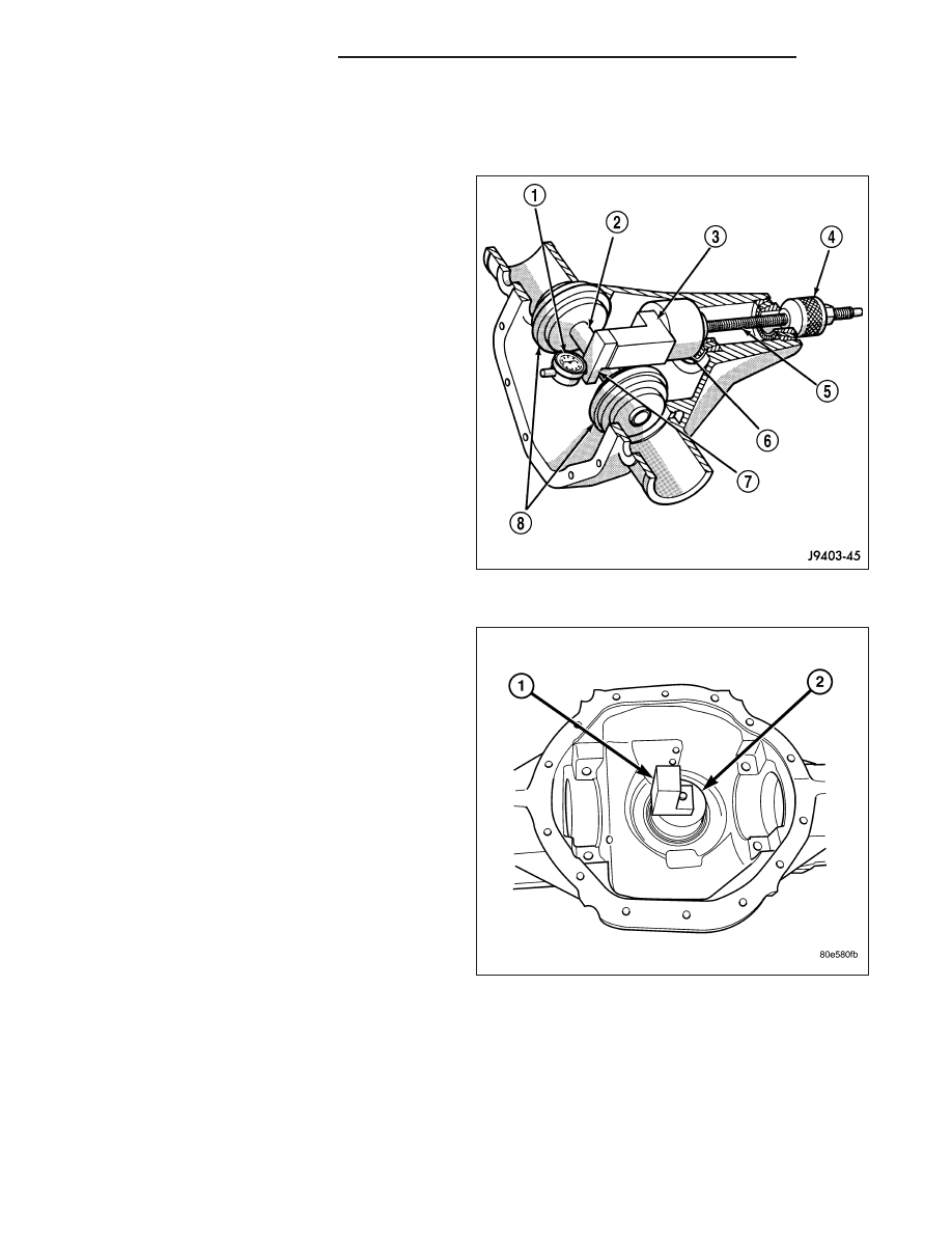
1. Assemble Pinion Height Block 6739 (3), Pinion

Block 8878 (6) and rear pinion bearing onto Screw
6741(5).

2. Insert assembled pinion height block (1), pinion

block (2), rear bearing and screw into the housing
through pinion bearing cups.

3. Install front pinion bearing and Cone-Nut 6740 onto

the screw. Tighten cone-nut until Torque To Rotate
the screw is 1.7-2.26 N·m (15-20 in. lbs.).

3 - 188

FRONT AXLE - 9 1/4 AA

DR/DH

4. Place Arbor Disc 8289 (4) on Arbor D-115-3 (3) in

position in the housing side bearing cradles.

5. Install differential bearing caps on arbor discs and

snug the bearing cap bolts. Then cross tighten cap
bolts to 85 N·m (63 ft. lbs.).

NOTE: Arbor (3) should rotate freely in the arbor
disc (4).

6. Assemble Dial Indicator C-3339 (1) into Scooter

Block D-115-2 (3) and secure set screw.

7. Position Scooter Block/Dial Indicator flush on the

pinion height block. Hold scooter block and zero
the dial indicator (1).

8. Slowly slide the scooter block across the pinion

height block over to the arbor. Move scooter block
till dial indicator crests the arbor (2), then record
the highest reading.

9. Select a shim equal to the dial indicator reading.

10. Install the select shim between the rear pinion

bearing and the pinion gear head.

DR/DH

FRONT AXLE - 9 1/4 AA

3 - 189

DIFFERENTIAL BEARING PRELOAD AND GEAR BACKLASH

Backlash is adjusted by moving the adjusters in and
out or both. By moving the adjusters the case/ring
gear will move closer or further away from the pinion.
In most cases this adjustment can be used to achieve
the correct gear tooth pattern and set the case bear-
ing preload.

1. Remove adjuster lock bolts (3) and adjuster locks

(2).

2. Loosen the differential bearing caps.

3. Slide differential case (1) toward the pinion gear

until the gears make contact/zero backlash. If zero
backlash cannot be obtained, turn the pinion side
adjuster until zero backlash is obtained.

4. Holding the differential case toward the pinion gear,

turn bearing adjusters with Spanner Wrench 8883
until they make contact with the differential bear-
ings/cups.

5. Back off the ring gear side adjuster 4 holes, to

obtain initial ring gear backlash.

6. Install ring gear side adjuster lock and bolt. Do not

tighten adjuster lock bolt at this time.

7. Tighten pinion gear side adjuster firmly against the differential case bearing cup.

8. Rotate the pinion several times to seat the differential bearings.

9. Loosen pinion gear side adjuster until it is no longer in contact with the bearing cup, then tighten it until it makes

contact.

10. Tighten pinion gear side adjuster an additional:

New Bearings: 6 Adjuster Holes

Original Bearings: 4 Adjuster Holes

11. Install pinion gear side adjuster lock and bolt. Do not tighten adjuster lock bolt at this time.

12. Tighten bearing cap bolts to 85 N·m (63 ft. lbs.).

13. Tighten adjuster lock bolts to 25 N·m (18 ft. lbs.).

14. Measure ring gear backlash with a Dial Indicator

C-3339 (1) and Dial Indicator Stud L-4438 at eight
points around the drive side of the ring gear (2).
The

backlash

should

be

0.08-0.25

mm

(0.003-0.010 in) with a preferred backlash of 0.13-
0.18 mm (0.005-0.007 in).

NOTE: Backlash measurement should not vary
more than 0.05 mm (0.002 in) between measuring
points. If measurement does vary inspect the
gears for burrs, the differential case flange and
ring gear mounting.

3 - 190

FRONT AXLE - 9 1/4 AA

DR/DH

GEAR TOOTH CONTACT PATTERN

1. Wipe clean each tooth of the ring gear.

2. Apply gear marking compound to all of the ring

gear teeth.

3. Verify bearing cap bolts are torque to specification.

4. Apply the brakes lightly to create a 14 N·m (10 ft.

lbs.) pinion rotating torque.

5. Rotate the pinion/pinion yoke 4 full revolutions in

each directions.

6. Read gear tooth contact pattern.

Gear contact pattern is correct. Backlash and pinion
depth is correct.

Ring gear too far away from pinion gear, coast side
toe (1) and drive side heel (2). Decrease backlash, by
moving the ring closer to the pinion gear using the
adjusters.

Ring gear too close to pinion gear, drive side toe (1)
and coast side heel (2).. Increase backlash, by moving
the ring away from the pinion gear using the adjusters.

DR/DH

FRONT AXLE - 9 1/4 AA

3 - 191


Content   ..  87  88  89  90   ..