Dodge Ram Truck 1500-2500-3500. Manual - part 55


  Index      Dodge     Dodge Ram Truck 1500-2500-3500 - service repair manual 2005 year


Search            


Content   ..  53  54  55  56   ..


Dodge Ram Truck 1500-2500-3500. Manual - part 55


C144F-FRONT DIFFERENTIAL POSITION SENSOR LOW (CONTINUED)

3.

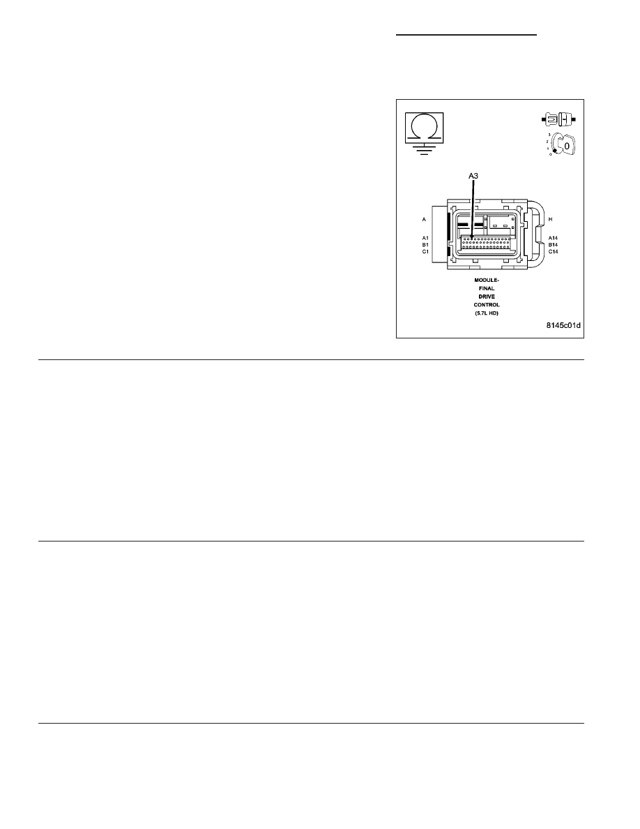
(T522) FRONT LOCKER SENSOR SENSE CIRCUIT SHORTED TO GROUND

Turn the ignition off.

Disconnect the FDCM harness connector.

Measure the resistance of the (T522) Front Locker Sensor Sense cir-
cuit in the FDCM harness connector.

Is the resistance below 5.0 ohms?

Yes

>> Repair the short to ground in the (T522) Front Locker Sen-

sor Sense circuit.

Perform FDCM VERIFICATION TEST.

No

>> Go To 4

4.

FDCM

NOTE: Before continuing, check the FDCM harness connector terminals for corrosion, damage, or terminal
push out. Repair as necessary.
Using the schematics as a guide, inspect the wire harness and connectors. Pay particular attention to all Power and
Ground circuits.

Were there any problems found?

Yes

>> Repair as necessary.

Perform FDCM VERIFICATION TEST

No

>> Replace and program the Final Drive Control Module in accordance with Service Information.

Perform FDCM VERIFICATION TEST.

5.

INTERMITTENT WIRING AND CONNECTORS

The conditions necessary to set this DTC are not present at this time.

Using the schematics as a guide, inspect the wiring and connectors specific to this circuit.

Wiggle test the wiring harness and connectors while checking for shorted and open circuits.

Using the DRBIII

T

, monitor the data related to this circuit while performing the wiggle test. Look for the data to

change or for the DTC to reset.

Were there any problems found?

Yes

>> Repair as necessary.

Perform FDCM VERIFICATION TEST.

No

>> Test Complete.

3 - 52

DIFFERENTIAL & DRIVELINE - ELECTRICAL DIAGNOSTICS

DR/DH

C1452-REAR DIFFERENTIAL POSITION SENSOR PERFORMANCE

DR/DH

DIFFERENTIAL & DRIVELINE - ELECTRICAL DIAGNOSTICS

3 - 53

C1452-REAR DIFFERENTIAL POSITION SENSOR PERFORMANCE (CONTINUED)

For a complete wiring diagram Refer to Section 8W.

When Monitored:
The ignition on. Axle Locker Switch in the RR or FR/RR position.

Set Condition:
The FDCM detects that the Rear Differential Position Sensor is in an unexpected state.

Possible Causes

REAR DIFFERENTIAL POSITION SENSOR (WIRING, CONNECTOR AND/OR TERMINAL CONDITION)

REAR DIFFERENTIAL POSITION SENSOR

REAR LOCKER SENSOR SENSE OPEN

FDCM

Diagnostic Test

1.

ACTIVE DTC

CAUTION: Before removing the FDCM harness connector, clean the connector and locking cam area of dirt
and debris. Failure to do so can result in the connector being jammed or damage to the locking cams on
the harness connector or module. Do not force the assist arm when releasing or installing the harness con-
nector.
Ignition on, engine not running.

With the DRBIII

T

, read DTCs.

Is the DTC active at this time?

Yes

>> Go To 2

No

>> Go To 6

2.

REAR DIFFERENTIAL POSITION SENSOR WIRING

NOTE: Before continuing with the below diagnostic test, ensure the FDCM harness connector seal is
installed correctly. Inspect the terminals on both harness connector and the module for damage. Failure to
do so can result in misdiagnoses of the system.
Using the DRBIII

T

, actuate the Rear Locker Solenoid.

Monitor the Rear Differential Position Sensor State.

Wiggle the related wiring harness from the FDCM to the Rear Locker Solenoid connector at the axle.

With a DRBIII

T

, actuate the Rear Locker Solenoid.

Does the state on the DRBIII

T

change while wiggling the wiring harness?

Yes

>> Using the schematics as a guide, inspect the wiring and connectors specific to this circuit. Check the

Locker Solenoid terminals and connectors for corrosion and/or dirty that may compromise the connec-
tion. Repair as necessary.

Perform FDCM VERIFICATION TEST.

No

>> Go To 3

3 - 54

DIFFERENTIAL & DRIVELINE - ELECTRICAL DIAGNOSTICS

DR/DH

C1452-REAR DIFFERENTIAL POSITION SENSOR PERFORMANCE (CONTINUED)

3.

REAR DIFFERENTIAL POSITION SENSOR OPERATION

Turn the ignition off.

Disconnect the Rear Locker Solenoid harness connector.

Ignition on, engine not running.

Using a jumper wire, jumper across from the (T527) Rear Locker Sensor Sense circuit and the (T521) Locker Sen-
sor Supply circuit in the Rear Locker Solenoid harness connector.

While monitoring the sensor state on the DRBIII

T

, tap the jumper wire on and off the (T527) Rear Locker Sensor

Sense circuit terminal. Hold the jumper wire on and off the terminal for a minimum of 3 seconds.

Does the state change on the DRBIII

T

while tapping the terminal?

Yes

>> Replace the Rear Locker Solenoid.

Perform FDCM VERIFICATION TEST.

No

>> Go To 4

4.

(T527) REAR LOCKER SENSOR SENSE CIRCUIT OPEN

Turn the ignition off.

Disconnect the FDCM harness connector.

Measure the resistance of the (T527) Rear Locker Sensor Sense cir-
cuit between the Rear Locker Solenoid harness connector and the
FDCM harness connector.

Is the resistance below 5.0 ohms?

Yes

>> Go To 5

No

>> Repair the open in the Rear Locker Sensor Sense circuit.

Perform FDCM VERIFICATION TEST.

5.

FDCM

NOTE: Before continuing, check the FDCM harness connector terminals for corrosion, damage, or terminal
push out. Repair as necessary.
Using the schematics as a guide, inspect the wire harness and connectors. Pay particular attention to all Power and
Ground circuits.

Were there any problems found?

Yes

>> Repair as necessary.

Perform FDCM VERIFICATION TEST

No

>> Replace and program the Final Drive Control Module in accordance with Service Information.

Perform FDCM VERIFICATION TEST.

DR/DH

DIFFERENTIAL & DRIVELINE - ELECTRICAL DIAGNOSTICS

3 - 55


Content   ..  53  54  55  56   ..