Dodge Neon / Neon SRT-4. Manual - part 376
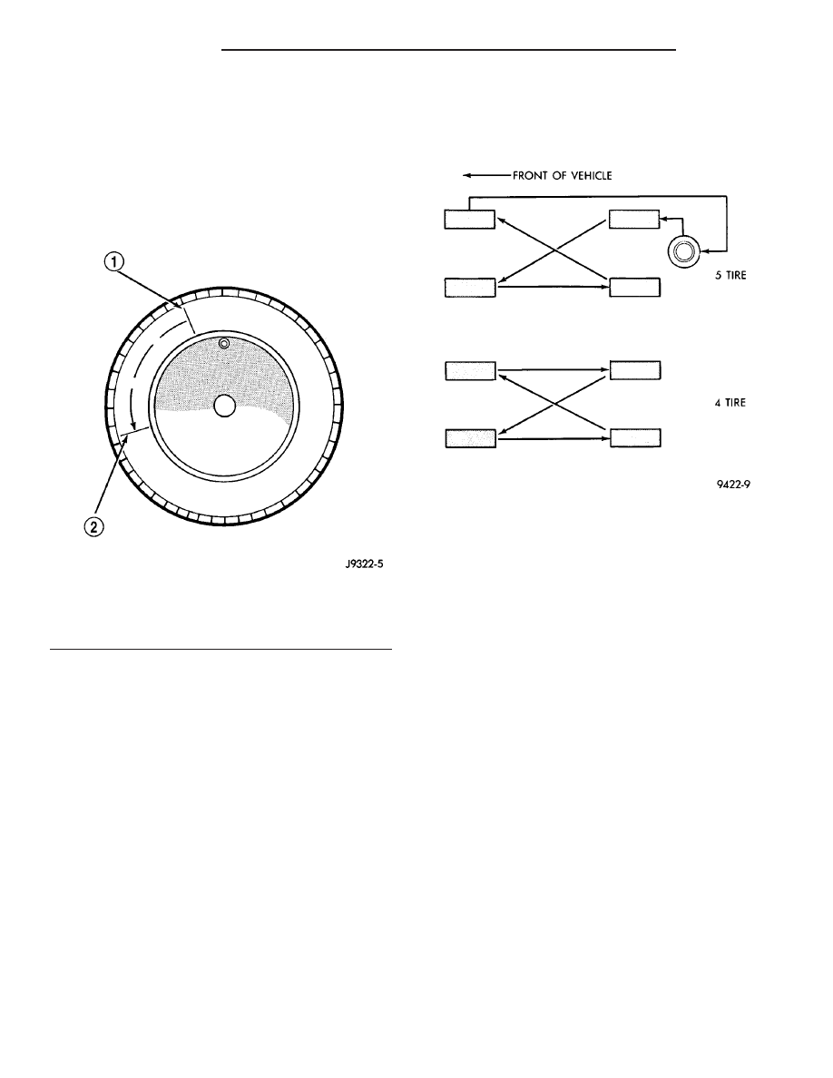
• If the new high spot is within 102 mm (4.0 in.)
of the first spot on the wheel, the wheel may be out
of specifications. Refer to Tire and Wheel Runout.
• If the new high spot is NOT within 102 mm (4.0
in.) of either high spot, draw an arrow on the tread
from new high spot to first. Break down the tire and
remount it 90 degrees on rim in that direction (Fig.
12), then remeasure runout. This procedure will nor-
mally reduce the runout to an acceptable amount.
STANDARD PROCEDURE - TIRE AND WHEEL
ROTATION
NON-DIRECTIONAL TREAD PATTERN TIRES
Tires on the front and rear axles operate at differ-
ent loads and perform different functions. For these
reasons, they wear at unequal rates, and tend to
develop irregular wear patterns. These effects can be
reduced by timely rotation of tires. The benefits of
rotation are especially worthwhile. Rotation will
increase tread life, help to maintain mud, snow, and
wet traction levels, and contribute to a smooth, quiet
ride.
The suggested rotation method is the forward-cross
tire rotation method (Fig. 13). This method takes
advantage of current tire industry practice which
allows rotation of radial-ply tires. Other rotation
methods may be used, but may not have all the ben-
efits of the recommended method.
NOTE: Only the 4 tire rotation method may be used
if the vehicle is equipped with a low mileage or tem-
porary spare tire.
DIRECTIONAL TREAD PATTERN TIRES
Some vehicles are fitted with special high-perfor-
mance tires having a directional tread pattern. These
tires are designed to improve traction on wet pave-
ment. To obtain the full benefits of this design, the
tires must be installed so that they rotate in the cor-
rect direction. This is indicated by arrows on the tire
sidewalls.
When wheels and tires are being installed, extra
care is needed to ensure that this direction of rota-
tion is maintained.
Refer to Owner’s Manual for rotation schedule.
REMOVAL
REMOVAL - TIRE AND WHEEL ASSEMBLY
(ALUMINUM WHEEL)
(1) Raise the vehicle. (Refer to LUBRICATION &
MAINTENANCE/HOISTING - STANDARD PROCE-
DURE)
(2) If the wheel has a large center cap that covers
the wheel mounting nuts, remove the cap by prying
it off.
(3) Remove the wheel mounting nuts from the
studs.
(4) Remove the tire and wheel assembly from the
hub.
Fig. 12 Remount Tire 90 Degrees In Direction of
Arrow
1 - 2ND HIGH SPOT ON TIRE
2 - 1ST HIGH SPOT ON TIRE
Fig. 13 Forward-Cross Tire Rotation Method
22 - 6
TIRES/WHEELS
PL/SRT-4
TIRES/WHEELS (Continued)