Dodge Neon / Neon SRT-4. Manual - part 375
 

  Index      Dodge     Dodge Neon / Neon SRT-4 - service repair manual 2005 year


Search            


Content   ..  373  374  375  376   ..


Dodge Neon / Neon SRT-4. Manual - part 375


METHOD 1 (RELOCATE WHEEL ON HUB)

Check accuracy of the wheel mounting surface;

adjust wheel bearings (if applicable).

Drive vehicle a short distance to eliminate tire flat

spotting from a parked position.

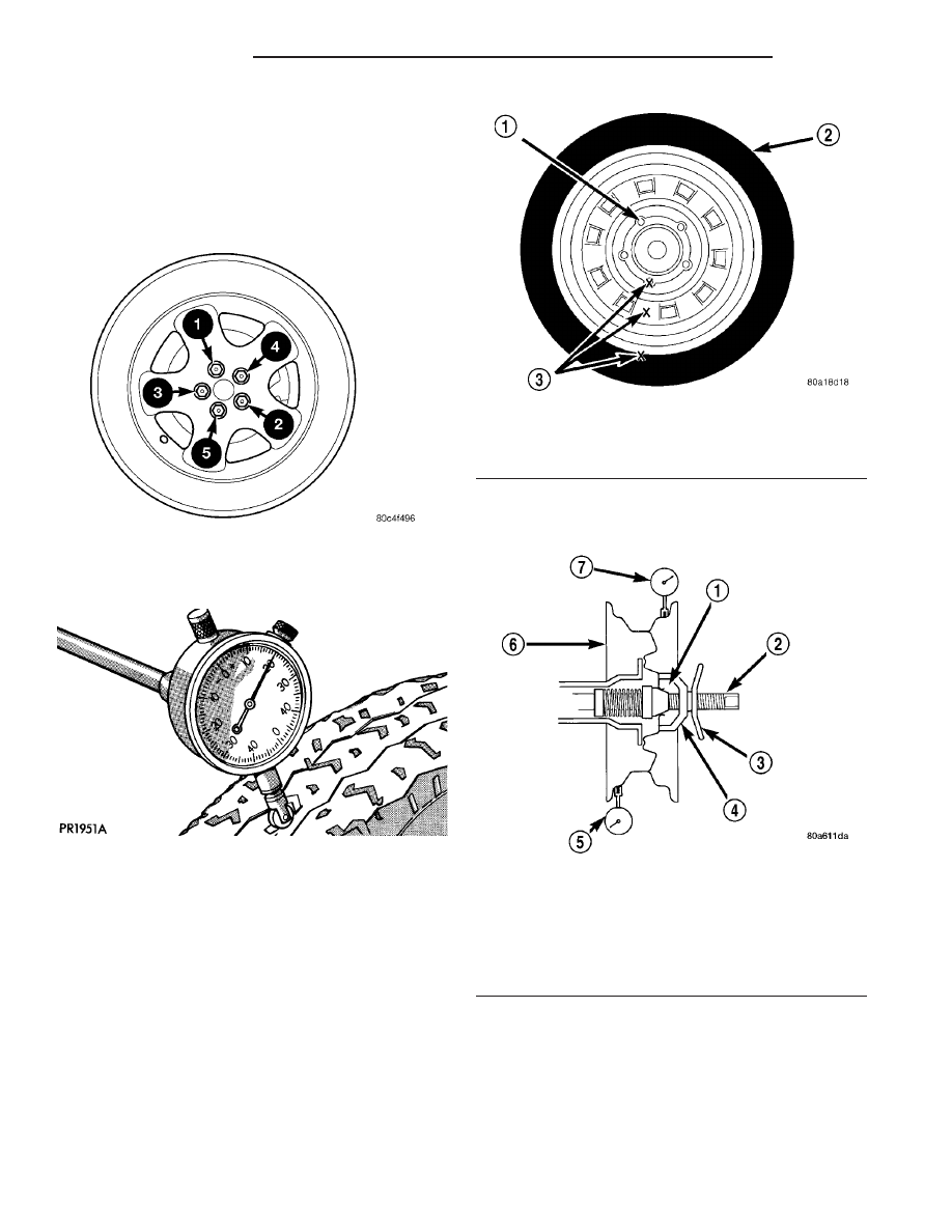
Verify all wheel nuts are tightened and torqued in

the correct sequence (Fig. 1).

Use runout gauge D-128-TR to determine runout

(Fig. 2).

Relocate the wheel on the mounting studs, two

studs over from the original position.

Retighten

wheel

nuts

until

all

are

properly

torqued. This will prevent brake distortion.

Check radial runout. If still excessive, mark tire

sidewall, wheel, and stud at point of maximum
runout (Fig. 3) and proceed to Method 2.

METHOD 2 (RELOCATE TIRE ON WHEEL)

Rotating tire on wheel is particularly effective

when there is runout in both tire and wheel.

Remove tire from wheel and remount wheel on hub

in former position.

Check the radial runout of the wheel (Fig. 4). The

radial runout should be no more than 0.762 mm
(0.030 inch).

Check the lateral runout of the wheel (Fig. 5). The

lateral runout should be no more than 0.762 mm
(0.030 inch).

If the point of greatest wheel radial runout is near

the original chalk mark, remount the tire on the rim
180 degrees from its original position. Recheck the
runout. If this does not reduce the runout to an
acceptable level, replace the wheel or the tire.

Fig. 1 Wheel Tightening Sequence

Fig. 2 Runout Gauge

Fig. 3 Chalk Marking On Wheel, Tire And Stud

1 - STUD
2 - TIRE
3 - CHALK MARK LOCATIONS

Fig. 4 Checking Wheel Radial Runout

1 - MOUNTING CONE
2 - SPINDLE SHAFT
3 - WING NUT
4 - PLASTIC CUP
5 - DIAL INDICATOR
6 - WHEEL
7 - DIAL INDICATOR

22 - 2

TIRES/WHEELS

PL/SRT-4

TIRES/WHEELS (Continued)

STANDARD PROCEDURE

STANDARD PROCEDURE - TIRE AND WHEEL
BALANCE

NOTE: Balance equipment must be calibrated and
maintained per equipment manufacturer’s specifica-
tions.

Wheel balancing can be accomplished with either

on-vehicle or off-vehicle equipment.

NOTE: If using on-vehicle balancing equipment, on
the driving axle, remove the opposite wheel and tire
assembly.

It is recommended that a two-plane dynamic bal-

ancer be used when a wheel and tire assembly
requires balancing. A static balancer should only be
used when a two-plane balancer is not available.

Balance wheel and tire assemblies dynamically and

statically to less than 0.25 (

1

4

) ounce.

For static balancing, find location of heavy spot

causing imbalance. Counter balance wheel directly
opposite the heavy spot. Determine weight required
to counterbalance the area of imbalance. Place half of
this weight on the inner rim flange and the other
half on the outer rim flange (Fig. 6).

Fig. 6 Static Unbalance & Balance

1 - HEAVY SPOT

4 - CORRECTIVE WEIGHT LOCATION

2 - CENTER LINE OF SPINDLE

5 - TIRE OR WHEEL TRAMP, OR WHEEL HOP

3 - ADD BALANCE WEIGHTS HERE

Fig. 5 Checking Wheel Lateral Runout

1 - MOUNTING CONE
2 - SPINDLE SHAFT
3 - WING NUT
4 - PLASTIC CUP
5 - DIAL INDICATOR
6 - WHEEL
7 - DIAL INDICATOR

PL/SRT-4

TIRES/WHEELS

22 - 3

TIRES/WHEELS (Continued)

For dynamic balancing, the balance equipment is

designed to indicate the location and amount of
weight to be applied to both the inner and outer rim
flanges (Fig. 7).

Aluminum wheels use unique wheel weights (Fig.

8). Each wheel weight is designed to fit the contoured
surface of the wheel (Fig. 8). When balancing an alu-
minum wheel, the correct wheel weight must be
used. Do not use any other type of wheel weight. It
will not properly fit the contour of the wheel.

Always verify the Balance. When using off-vehicle

equipment, rotate assembly 180 degrees on balance
equipment to verify balance. Variation should not be
more than 0.125 (

1

8

) ounce. If variation is more than

0.125 ounce, balancing equipment could be malfunc-
tioning.

If difficult to balance, break down the wheel and

tire assembly and check for loose debris inside tire.
Prior to disassembly, mark (index) the tire at the
valve stem. Use this mark in order to remount the
tire in its original orientation with respect to the
wheel.

STANDARD PROCEDURE - TIRE AND WHEEL
BALANCE - SRT-4

NOTE: Balance equipment must be calibrated and
maintained per equipment manufacturer’s specifica-
tions to achieve preferred results.

It is recommended that a two-plane dynamic bal-

ancer designed to balance using stick-on type wheel
weights be used when a wheel and tire assembly
requires

balancing.

Static

balancing

equipment

should only be used when a two-plane balancer is not
available. Balance tire and wheel assemblies to less
than 0.25 (

1

4

) ounce (7.0 grams) imbalance.

This vehicle is equipped with wheels that do not

have a flange on the outer face. For that reason,
clip-on wheel weights cannot be used on the outer
face of any wheel and must not be used on the inner
face due to clearance issues. In their place, stick-on

Fig. 7 Dynamic Unbalance & Balance

1 - CENTER LINE OF SPINDLE

3 - CORRECTIVE WEIGHT LOCATION

2 - ADD BALANCE WEIGHTS HERE

4 - HEAVY SPOT WHEEL SHIMMY AND VIBRATION

Fig. 8 Aluminum Wheel Weight

1 - TIRE
2 - WHEEL
3 - WHEEL WEIGHT

22 - 4

TIRES/WHEELS

PL/SRT-4

TIRES/WHEELS (Continued)

type weights must be used. Wheel weights may be
placed in locations indicated in figure (Fig. 9).

STANDARD PROCEDURE - TIRE AND WHEEL
MATCH MOUNTING

Steel wheels and tires are match mounted at the

factory. This means that the high spot of the tire is
matched to the low spot on the wheel rim. This tech-
nique is used to reduce runout in the wheel/tire
assembly. The high spot on the tire is marked with a
paint mark or a bright colored adhesive label on the
outboard sidewall. The low spot on the rim is identi-
fied with a label on the outside of the rim and a dot
or line in the drop well on the tire side of the rim. If
the outside label has been removed the tire will have
to be removed to locate the dot or line on the inside
of the rim.

Before dismounting a tire from its wheel, a refer-

ence mark should be placed on the tire at the valve
stem location. This reference will ensure that it is
remounted in the original position on the wheel.

(1) Measure the total indicator runout on the cen-

ter of the tire tread rib. Record the indicator reading.
Mark the tire to indicate the high spot. Place a mark
on the tire at the valve stem location (Fig. 10).

(2)

Break down the tire and remount it 180

degrees on the rim (Fig. 11).

(3) Measure the total indicator runout again. Mark

the tire to indicate the high spot.

(4) If runout is still excessive (in excess of 1.524

mm or 0.060 in.), the following procedures must be
done.

• If the new high spot is within 102 mm (4.0 in.)

of the first spot on the tire and is still excessive,
replace the tire.

Fig. 9 Wheel Weight Locations

1 - WHEEL
2 - CLIP-ON WHEEL WEIGHT (DO NOT USE)
3 - INNER FACE OF WHEEL
4 - STICK-ON WHEEL WEIGHT (INNER LOCATION)
5 - STICK-ON WHEEL WEIGHT (OUTER LOCATION)
6 - OUTER FACE OF WHEEL

Fig. 10 First Measurement On Tire

1 - REFERENCE MARK
2 - 1ST MEASUREMENT

HIGH SPOT MARK TIRE AND RIM
3 - WHEEL
4 - VALVE STEM

Fig. 11 Remount Tire 180 Degrees

1 - VALVE STEM
2 - REFERENCE MARK

PL/SRT-4

TIRES/WHEELS

22 - 5

TIRES/WHEELS (Continued)


Content   ..  373  374  375  376   ..