Dodge Neon / Neon SRT-4. Manual - part 235
CAUTION: When installing the intake rocker arm
shaft assembly be sure that the plastic spacers do
not interfere with the spark plug tubes. If the spac-
ers do interfere rotate until they are at the proper
angle. To avoid damaging the spark plug tubes, do
not attempt rotating the spacers by forcing down
the shaft assembly.
(4) Verify that hydraulic lash adjuster swivel feet
are still in place.
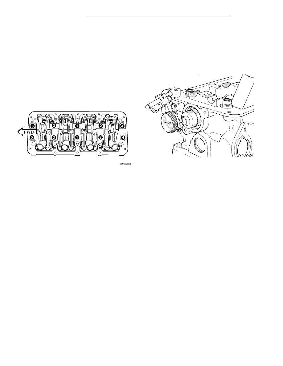
(5) Tighten bolts to 28 N·m (250 in. lbs.) in
sequence shown in (Fig. 28).
(6) Install the cylinder head cover (Refer to 9 -
ENGINE/CYLINDER
HEAD/CYLINDER
HEAD
COVER(S) - INSTALLATION).
CAMSHAFT
DESCRIPTION
The camshaft is made of nodular iron with five
bearing journal surfaces and three cam lobes per cyl-
inder. Provision for a cam position sensor is provided
on the rear of the camshaft. The camshaft position
sensor bolts to the rear of the cylinder head and also
controls camshaft thrust. A hydrodynamic oil seal is
used for oil control at the front of the camshaft.
OPERATION
The camshaft is driven by the crankshaft via drive
sprockets and belt. The camshaft has precisely
machined lobes to provide accurate valve timing and
duration.
STANDARD PROCEDURE - CAMSHAFT
END-PLAY
(1) Measure camshaft end play using the following
procedure:
(a) Mount dial indicator C-3339 or equivalent, to
a stationary point on cylinder head (Fig. 29).
(b) Using a suitable tool, move camshaft to rear-
ward limits of travel.
(c) Zero the dial indicator.
(d) Move camshaft forward to limits of travel
and read dial indicator.
(e) End play travel: 0.13–0.33 mm (0.005–0.013
in.).
REMOVAL
(1) Disconnect and isolate negative battery cable.
(2) Disconnect positive battery cable. Remove the
battery (Refer to 8 - ELECTRICAL/BATTERY SYS-
TEM/BATTERY - REMOVAL).
(3) Disconnect the IAT sensor electrical connector
(Refer to 14 - FUEL SYSTEM/FUEL INJECTION/IN-
LET AIR TEMPERATURE SENSOR - DESCRIP-
TION) .
(4) Disconnect the following:
• Air intake duct at throttle body
• Throttle cables
• TPS and IAC connectors
• Make-up air hose at air cleaner housing
(5) Remove the air cleaner housing assembly
(Refer to 9 - ENGINE/AIR INTAKE SYSTEM/AIR
CLEANER HOUSING - REMOVAL).
(6) Remove the battery tray. (Refer to 8 - ELEC-
TRICAL/BATTERY SYSTEM/TRAY - REMOVAL)
(7) Remove the front timing belt cover, timing belt,
and tensioner (Refer to 9 - ENGINE/VALVE TIMING/
TIMING BELT AND SPROCKETS - REMOVAL).
(8) Remove the camshaft sprocket and rear timing
belt cover (Refer to 9 - ENGINE/VALVE TIMING/
TIMING BELT COVER(S) - REMOVAL).
(9) Remove the cylinder head cover (Refer to 9 -
ENGINE/CYLINDER
HEAD/CYLINDER
HEAD
COVER(S) - REMOVAL).
(10) Mark rocker arm shaft assemblies so that
they are installed in their original positions.
Fig. 28 Rocker Arm Shaft Tightening Sequence
Fig. 29 Camshaft End Play
9 - 34
ENGINE 2.0L SOHC
PL/SRT-4
ROCKER ARM / HYDRAULIC LASH ADJUSTER ASSEMBLY (Continued)