Dodge Neon / Neon SRT-4. Manual - part 233
 

  Index      Dodge     Dodge Neon / Neon SRT-4 - service repair manual 2005 year


Search            


Content   ..  231  232  233  234   ..


Dodge Neon / Neon SRT-4. Manual - part 233


AIR CLEANER HOUSING

REMOVAL

(1) Unlatch 2 clips and rotate the lid upward and

off of the air cleaner box.

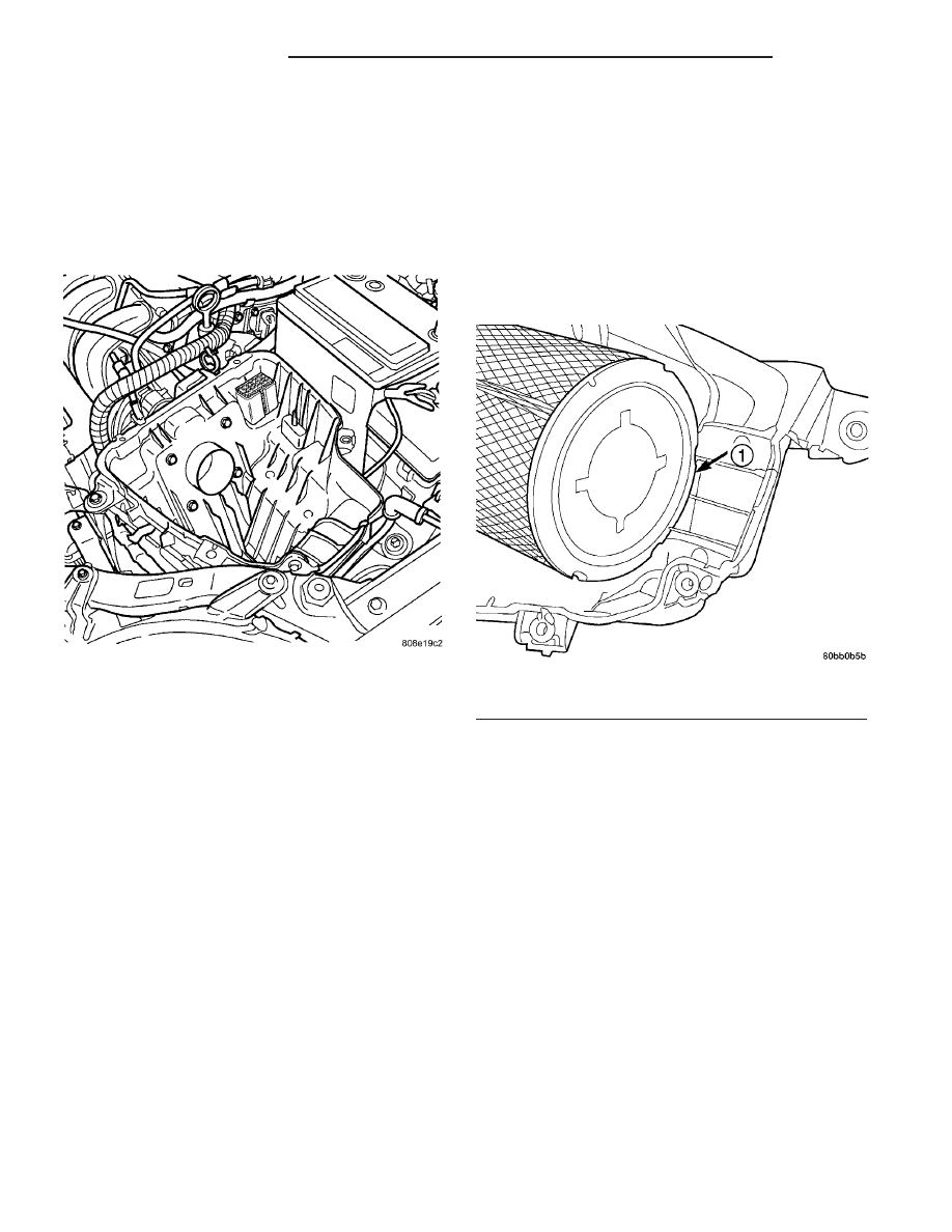
(2) Pull air filter up and out of air cleaner box

(Fig. 12).

(3) Remove the 4 bolts from the air cleaner box to

throttle body.

(4) Remove the make-up air hose from the air

cleaner box.

(5) Remove the bolt and nut from the air cleaner

box.

(6) Remove wiring harness from the clips on the

side of the air cleaner box.

(7) Remove the wiring clip from the front of the air

cleaner box.

(8) Disconnect the vacuum harness from the throt-

tle body and body harness.

(9) Pull air cleaner box up and off of stud and bat-

tery tray and remove from vehicle.

INSTALLATION

(1) Install air cleaner box. Make sure that it is on

the battery tray tab in the back and on the stud on
the side.

(2) Install the bolts to the throttle body and

tighten.

(3) Connect the make-up air hose to the air

cleaner box.

(4) Connect the vacuum harness to the throttle

body and body harness.

(5) Install the wiring clip in the front of the air

cleaner box.

(6) Install the wiring harness into the clips on the

side of the air cleaner box.

(7) Install the nut and bolt for air cleaner box and

tighten to 7.3 N·m (65 in. lbs.).

(8) Install inlet elbow to air cleaner box and

fender.

(9) Install air filter element on to throttle body

and push towards the throttle body and past lip in
air cleaner box bottom (Fig. 13).

(10) Install lid and latch the 2 clips.

CYLINDER HEAD

DESCRIPTION

The cross flow designed, aluminum cylinder head

contains a single over head camshaft with four valves
per cylinder (Fig. 14). The valves are arranged in two
in-line banks. The intake valves face toward the
front of the vehicle. The exhaust valves face the dash
panel. The cylinder head incorporates powdered
metal valve guides and seats. The cylinder head is
sealed to the block using a head gasket and retaining
bolts.

The rocker arm shafts mount directly to the cylin-

der head. The rocker arms shafts are hollow, provid-
ing

lubrication

passages

to

the

hydraulic

lash

adjusters, camshaft, and valve mechanisms.

Fig. 12 Air Cleaner Box

Fig. 13 Air Cleaner Box Lip

1 - LIP

9 - 26

ENGINE 2.0L SOHC

PL/SRT-4

DIAGNOSIS AND TESTING

CYLINDER HEAD GASKET

A cylinder head gasket leak can be located between

adjacent cylinders or between a cylinder and the
adjacent water jacket.

Possible indications of the cylinder head gasket

leaking between adjacent cylinders are:

• Loss of engine power

• Engine misfiring

• Poor fuel economy
Possible indications of the cylinder head gasket

leaking between a cylinder and an adjacent water
jacket are:

• Engine overheating

• Loss of coolant

• Excessive steam (white smoke) emitting from

exhaust

• Coolant foaming

CYLINDER-TO-CYLINDER LEAKAGE TEST

To determine if an engine cylinder head gasket is

leaking between adjacent cylinders, follow the proce-
dures in Cylinder Compression Pressure Test (Refer
to 9 - ENGINE - DIAGNOSIS AND TESTING). An
engine cylinder head gasket leaking between adja-
cent cylinders will result in approximately a 50–70%
reduction in compression pressure.

CYLINDER-TO-WATER JACKET LEAKAGE TEST

WARNING: USE EXTREME CAUTION WHEN THE
ENGINE IS OPERATING WITH COOLANT PRES-
SURE CAP REMOVED.

VISUAL TEST METHOD

With the engine cool, remove the coolant pressure

cap. Start the engine and allow it to warm up until
thermostat opens.

If a large combustion/compression pressure leak

exists, bubbles will be visible in the coolant.

COOLING SYSTEM TESTER METHOD

WARNING: WITH COOLING SYSTEM TESTER IN
PLACE, PRESSURE WILL BUILD UP FAST. EXCES-
SIVE

PRESSURE

BUILT

UP,

BY

CONTINUOUS

ENGINE OPERATION, MUST BE RELEASED TO A
SAFE PRESSURE POINT. NEVER PERMIT PRES-
SURE TO EXCEED 138 kPa (20 psi).

Install Cooling System Tester 7700 or equivalent to

pressure cap neck. Start the engine and observe the
tester’s pressure gauge. If gauge pulsates with every
power stroke of a cylinder a combustion pressure
leak is evident.

CHEMICAL TEST METHOD

Combustion leaks into the cooling system can also

be checked by using Bloc-Chek Kit C-3685-A or
equivalent. Perform test following the procedures
supplied with the tool kit.

REMOVAL - CYLINDER HEAD

(1) Perform fuel system pressure release procedure

before attempting any repairs (Refer to 14 -
FUEL SYSTEM/FUEL DELIVERY - STANDARD
PROCEDURE).

(2) Disconnect negative battery cable.
(3) Remove power steering/air conditioning drive

belt (Refer to 7 - COOLING/ACCESSORY DRIVE/
DRIVE BELTS - REMOVAL).

(4) Raise vehicle on hoist.
(5) Drain cooling system (Refer to 7 - COOLING/

ENGINE - STANDARD PROCEDURE).

(6) Disconnect exhaust pipe from exhaust mani-

fold.

(7) Remove right front wheel.
(8) Remove accessory drive belt splash shield.
(9) Remove generator belt (Refer to 7 - COOLING/

ACCESSORY DRIVE/DRIVE BELTS - REMOVAL).

(10) Remove crankshaft vibration damper (Refer to

9

-

ENGINE/ENGINE

BLOCK/VIBRATION

DAMPER - REMOVAL).

(11) Remove lower torque strut (Refer to 9 -

ENGINE/ENGINE MOUNTING/TORQUE STRUT -
REMOVAL).

(12) Lower vehicle and remove upper torque strut

(Refer

to

9

-

ENGINE/ENGINE

MOUNTING/

TORQUE STRUT - REMOVAL).

(13) Remove ground strap and power steering hose

support clip from engine mount bracket.

(14) Remove power steering pump assembly and

set aside.

(15) Support engine from beneath with a suitable

jack.

(16) Remove right side engine mount to bracket

through bolt.

(17) Remove the lower engine mount bracket bolt.

Raise engine slightly and remove the upper engine
mount bracket bolts.

(18) Remove the engine mount bracket. This proce-

dure may require additional raising/lowering of
engine until bracket will clear engine components
(Refer to 9 - ENGINE/ENGINE MOUNTING/EN-
GINE MOUNT BRACKET - REMOVAL).

(19) Remove front timing belt cover (Refer to 9 -

ENGINE/VALVE TIMING/TIMING BELT COVER(S)
- REMOVAL).

(20) Rotate engine until timing marks are aligned.
(21) Remove timing belt (Refer to 9 - ENGINE/

VALVE TIMING/TIMING BELT AND SPROCKETS -
REMOVAL).

PL/SRT-4

ENGINE 2.0L SOHC

9 - 27

CYLINDER HEAD (Continued)

(22) Remove timing belt tensioner/bracket assem-

bly (Refer to 9 - ENGINE/VALVE TIMING/TIMING
BELT TENSIONER & PULLEY - REMOVAL).

(23) Remove camshaft sprocket (Refer to 9 -

ENGINE/VALVE

TIMING/TIMING

BELT

AND

SPROCKETS - REMOVAL).

(24) Remove rear timing belt cover (Refer to 9 -

ENGINE/VALVE TIMING/TIMING BELT COVER(S)
- REMOVAL).

(25) Disconnect fuel line at fuel rail (Refer to 14 -

FUEL

SYSTEM/FUEL

DELIVERY/QUICK

CON-

NECT FITTING - STANDARD PROCEDURE).

(26) Remove coolant recovery container (Refer to 7

- COOLING/ENGINE/COOLANT RECOVERY CON-
TAINER - REMOVAL).

(27) Remove ground strap to cylinder head.
(28) Remove upper radiator hose.

(29) Remove

intake

manifold

(Refer

to

9

-

ENGINE/MANIFOLDS/INTAKE

MANIFOLD

-

REMOVAL).

(30) Disconnect ignition coil electrical connector.
(31) Remove ignition coil and spark plug cables

from engine.

(32) Remove make-up air hose from cylinder head

cover.

(33) Disconnect cam sensor and engine coolant

temperature (ECT) sensor electrical connectors.

(34) Remove heater tube to cylinder head attach-

ing fasteners.

(35) Remove heater hose from thermostat housing

connector.

(36) Remove cylinder head cover (Refer to 9 -

ENGINE/CYLINDER

HEAD/CYLINDER

HEAD

COVER(S) - REMOVAL).

(37) Remove cylinder head bolts.
(38) Remove cylinder head and gasket (Fig. 14).

Fig. 14 Cylinder Head Assembly

1 - ROCKER SHAFT RETAINING BOLT
2 - VALVE RETAINING LOCKS
3 - VALVE
4 - VALVE SPRING
5 - VALVE SEAL AND VALVE SPRING SEAT ASSEMBLY
6 - SPARK PLUG TUBE SEAL
7 - CAMSHAFT
8 - ROCKER ARM SHAFT RETAINER SPACER
9 - GASKET

10 - SPACER
11 - INTAKE ROCKER ARM/HYDRAULIC LASH ADJUSTER
ASSEMBLY
12 - EXHAUST ROCKER ARM/HYDRAULIC LASH ADJUSTER
ASSEMBLY
13 - CAMSHAFT SEAL
14 - RETAINER SPACER
15 - VALVE SPRING RETAINER

9 - 28

ENGINE 2.0L SOHC

PL/SRT-4

CYLINDER HEAD (Continued)

CLEANING

To ensure engine gasket sealing, proper surface

preparation must be performed, especially with the
use of aluminum engine components and multi-layer
steel cylinder head gaskets.

NOTE: Multi-Layer Steel (MLS) head gaskets require
a scratch free sealing surface.

Remove all gasket material from cylinder head and

block (Refer to 9 - ENGINE - STANDARD PROCE-
DURE). Be careful not to gouge or scratch the alumi-
num head sealing surface.

Clean all engine oil passages.

INSPECTION

(1)

Cylinder head must be flat within 0.1 mm

(0.004 in.) (Fig. 15).

(2)

Inspect camshaft bearing journals for scoring.

(3) Remove carbon and varnish deposits from

inside of valve guides with a reliable guide cleaner.

(4) Using a small hole gauge and a micrometer,

measure valve guides in 3 places top, middle and bot-
tom (Fig. 16). (Refer to 9 - ENGINE - SPECIFICA-
TIONS) Replace guides if they are not within
specification.

(5) Check valve guide height (Fig. 17).

INSTALLATION - CYLINDER HEAD

EXAMINING CYLINDER HEAD BOLTS

NOTE: The cylinder head bolts should be examined
BEFORE reuse. If the threads are necked down, the
bolt(s) should be replaced (Fig. 18).

Necking can be checked by holding a scale or

straight edge against the threads. If all the threads
do not contact the scale, the bolt(s) should be
replaced.

Fig. 15 Checking Cylinder Head Flatness

1 - FEELER GAUGE
2 - STRAIGHT EDGE

Fig. 16 Checking Wear on Valve Guide—Typical

1 - TOP
2 - MIDDLE
3 - BOTTOM
4 - CUT AWAY VIEW OF VALVE GUIDE MEASUREMENT
LOCATIONS

Fig. 17 Valve Guide Height

1 - VALVE GUIDE
2 - 13.25 - 13.75 MM (0.521 - 0.541 IN.)
3 - SPRING SEAT

Fig. 18 Checking Bolts for Stretching (Necking)

1 - STRETCHED BOLT
2 - THREADS ARE NOT STRAIGHT ON LINE
3 - THREADS ARE STRAIGHT ON LINE
4 - UNSTRETCHED BOLT

PL/SRT-4

ENGINE 2.0L SOHC

9 - 29

CYLINDER HEAD (Continued)


Content   ..  231  232  233  234   ..