Dodge Neon / Neon SRT-4. Manual - part 42
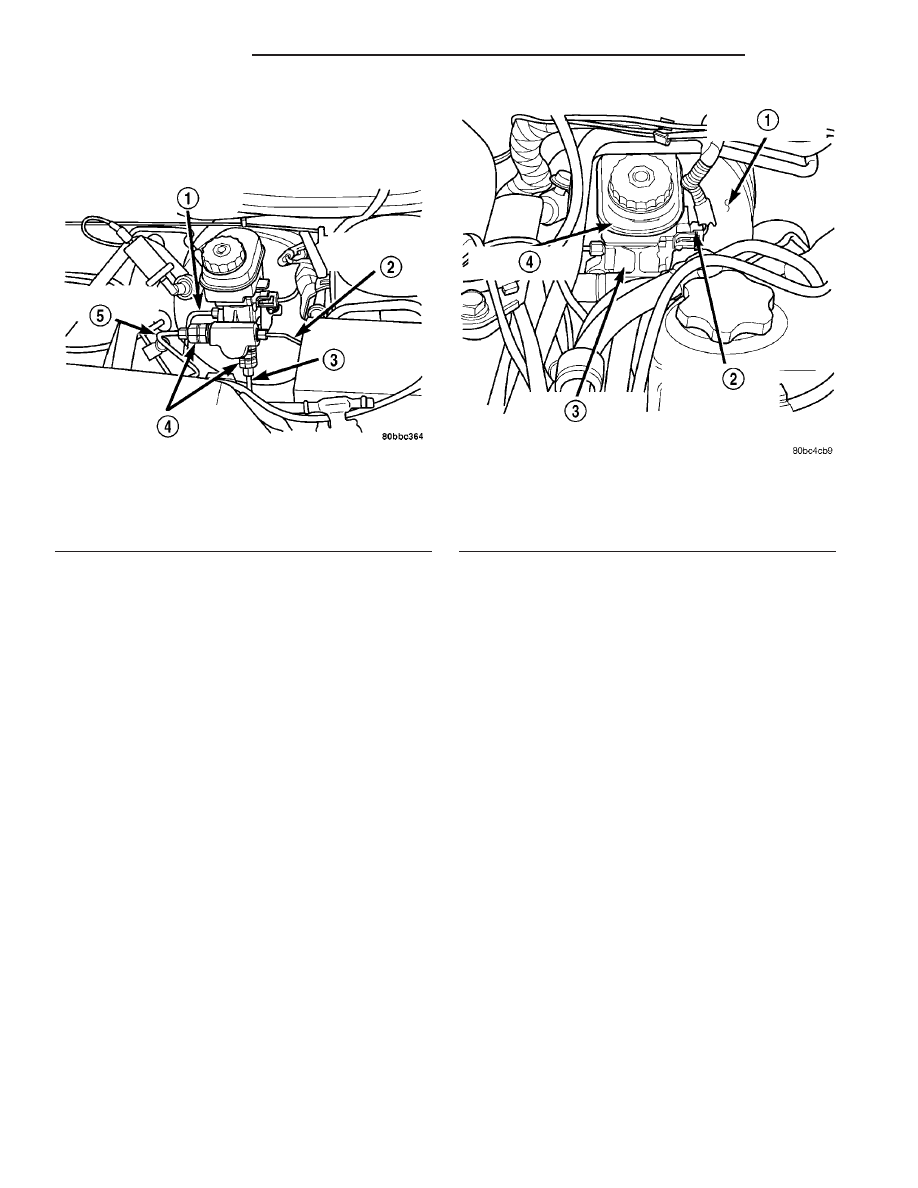
(5) Disconnect the two brake tubes from the mas-
ter cylinder, and two brake tubes from the propor-
tioning valves (Fig. 96). Install plugs at all of the
open brake tube outlets on the master cylinder.
(6) Clean the area around where the master cylin-
der attaches to the power brake booster using a suit-
able brake cleaner such as Mopar Brake Parts
Cleaner or an equivalent.
(7) Remove the two nuts attaching the master cyl-
inder to the power brake booster.
(8) Slide the master cylinder straight out of the
power brake booster.
(9) To remove the proportioning valves, unthread
each from the master cylinder.
REMOVAL - RHD
NOTE: Before proceeding, (Refer to 5 - BRAKES -
WARNING).
CAUTION: The vacuum in the power brake booster
must be pumped down before removing the master
cylinder to prevent the booster from sucking in any
contamination. This can be done by pumping the
brake pedal while the engine is not running until a
firm brake pedal is achieved.
(1) With the engine not running, pump the brake
pedal 4-5 strokes until the pedal feel is firm.
(2) Disconnect the negative (ground) cable from
the battery and isolate the cable.
(3) Disconnect the brake fluid level switch wiring
connector (Fig. 97).
(4) Remove the brake lines from the master cylin-
der.
(5) Remove the (2) master cylinder mounting nuts.
(6) Slide the master cylinder assembly straight out
of the power brake booster.
INSTALLATION
INSTALLATION - LHD WITH ABS
NOTE: The master cylinder must be bled before
installing it on the vehicle.
(1) Bleed the master cylinder before installing it
on the vehicle. (Refer to 5 - BRAKES - ABS/HY-
DRAULIC/MECHANICAL/MASTER
CYLINDER
-
STANDARD PROCEDURE).
(2) Inspect and wipe clean the O-ring vacuum seal
on the master cylinder rear mounting flange to
ensure a good vacuum seal once installation is com-
plete. Replace as necessary.
(3) Wipe the face of the power brake booster clean
where the master cylinder seal comes in contact
when it’s installed. Do not get any cleaner or debris
inside the booster.
(4) Position the master cylinder on the studs of
power brake vacuum booster aligning the booster
push rod with the master cylinder push rod. Care-
fully push the master cylinder onto the studs until it
contacts the face of the booster.
Fig. 96 Brake Tubes At Master Cylinder
1 - RIGHT FRONT BRAKE TUBE
2 - LEFT FRONT BRAKE TUBE
3 - LEFT REAR BRAKE TUBE
4 - REAR PROPORTIONING VALVES
5 - RIGHT REAR BRAKE TUBE
Fig. 97 RHD MASTER CYLINDER
1 - POWER BRAKE VACUUM BOOSTER
2 - BRAKE FLUID LEVEL SWITCH
3 - MASTER CYLINDER
4 - BRAKE FLUID RESERVOIR
5 - 50
BRAKES - BASE
PL/SRT-4
MASTER CYLINDER (Continued)