Dodge Neon / Neon SRT-4. Manual - part 13
REMOVAL
NOTE: Before proceeding, review all Warnings and
Cautions. (Refer to 2 - SUSPENSION/FRONT -
WARNING)
(1) Apply the brakes and hold in place.
(2) Raise the vehicle. (Refer to LUBRICATION &
MAINTENANCE/HOISTING - STANDARD PROCE-
DURE)
(3) Remove the front tire and wheel assembly.
(4) Remove the cotter pin, lock nut and spring
washer from the hub nut (Fig. 2).
(5) While the brakes are applied, loosen and
remove the hub nut on the end of the driveshaft (Fig.
2).
(6) Release the brakes.
(7) Remove
the
front
disc
brake
caliper
and
adapter as an assembly, and the brake rotor from the
steering knuckle. (Refer to 5 - BRAKES/HYDRAU-
LIC/MECHANICAL/ROTOR - REMOVAL)
(8) Remove the nut attaching the outer tie rod to
the steering knuckle. To do this, hold the tie rod end
stud with a wrench while loosening and removing the
nut with a standard wrench or crowfoot wrench (Fig.
4).
(9) Remove the tie rod end from the steering
knuckle using Remover, Special Tool MB991113 (Fig.
5).
(10) Remove the tie rod heat shield.
(11) Remove the nut and pinch bolt clamping the
ball joint stud to the steering knuckle (Fig. 6).
CAUTION: The strut assembly-to-steering knuckle
attaching bolts are serrated and must not be turned
during removal. Hold the bolts stationary in the
steering knuckles while removing the nuts, then tap
the bolts out using a pin punch.
(12) Remove the two bolts attaching the strut to
the steering knuckle.
NOTE: Use caution when separating the ball joint
stud from the steering knuckle, so the ball joint seal
does not get cut.
(13) Separate the ball joint stud from the steering
knuckle by prying down on lower control arm and up
against the ball joint boss on the steering knuckle
(Fig. 7).
NOTE: Do not allow the driveshaft to hang by the
inner C/V joint; it must be supported to keep the
joint from separating during this operation.
(14) Pull the steering knuckle off the driveshaft
outer C/V joint splines and remove the steering
knuckle.
NOTE: The cartridge type front wheel bearing used
on this vehicle is not transferable to the replace-
ment steering knuckle. If the replacement steering
knuckle does not come with a wheel bearing, a new
bearing must be installed in the steering knuckle.
Installation of the new wheel bearing and hub must
be done before installing the steering knuckle on
the vehicle.
(15) If the wheel bearing and hub need removal,
(Refer to 2 - SUSPENSION/FRONT/KNUCKLE -
DISASSEMBLY). Do not reuse the wheel bearing.
DISASSEMBLY - WHEEL BEARING AND HUB
NOTE: The removal and installation of the wheel
bearing and hub from the steering knuckle is only
to be done with the steering knuckle removed from
the vehicle using the following procedure.
(1) Remove steering knuckle, hub, and wheel bear-
ing as an assembly from the vehicle. (Refer to 2 -
SUSPENSION/FRONT/KNUCKLE - REMOVAL)
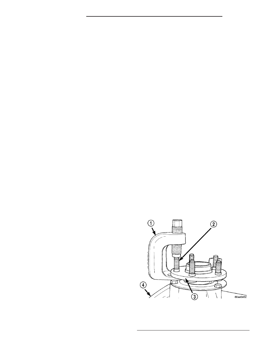
(2) Three wheel studs across from one another
require removal from the hub flange. Rotate the hub
to align each wheel mounting stud with the notch in
the bearing retainer plate before removal. Using
Remover, Special Tool C–4150A (Fig. 24), press the
three wheel mounting studs out of the hub flange.
Remove the wheel mounting studs from the hub
through the open notch (Fig. 25).
Fig. 24 Special Tool C-4150A
1 - SPECIAL TOOL C-4150A
2 - WHEEL MOUNTING STUD
3 - HUB FLANGE
4 - STEERING KNUCKLE
2 - 14
FRONT SUSPENSION
PL/SRT-4
KNUCKLE - SRT-4 (Continued)