Dodge Neon / Neon SRT-4. Manual - part 12
 

  Index      Dodge     Dodge Neon / Neon SRT-4 - service repair manual 2005 year


Search            


Content   ..  10  11  12  13   ..


Dodge Neon / Neon SRT-4. Manual - part 12


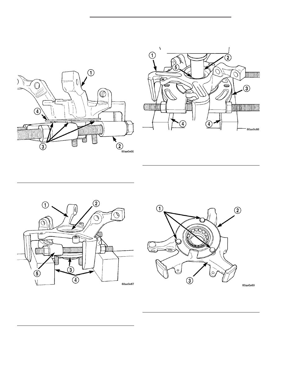
(5) Once the bearing splitter in fully installed, be

sure the three bolts attaching the bearing retainer
plate to steering knuckle (Fig. 12) are contacting the
bearing splitter (Fig. 12). The bearing retainer plate
should not support the steering knuckle or contact
the bearing splitter.

(6) Place the steering knuckle in an arbor press

supported by the bearing splitter as shown (Fig. 13).

(7) Position Driver, Special Tool 6644-2, on the

small end of the hub (Fig. 14). Using the arbor press,
remove the hub from the wheel bearing. The outer

bearing race will normally come out of the wheel
bearing when the hub is pressed out of the bearing.

(8) Remove the bearing splitter from the steering

knuckle.

(9) Remove the three bolts mounting the bearing

retainer plate to the steering knuckle (Fig. 15).
Remove the bearing retainer plate from the steering
knuckle.

(10) Place the steering knuckle back in the arbor

press supported by press blocks as shown (Fig. 16).
The press blocks must not obstruct the bore in the
steering knuckle so the wheel bearing can be pressed
out of the steering knuckle. Place Bearing Driver,
Special Tool MB-990799 on the outer race of wheel

Fig. 12 Correct Installation Of Bearing Splitter

1 - STEERING KNUCKLE
2 - SPECIAL TOOL 1130
3 - BEARING RETAINER PLATE MOUNTING BOLTS
4 - BEARING RETAINER PLATE

Fig. 13 Steering Knuckle Supporting For Hub

Removal

1 - STEERING KNUCKLE
2 - WHEEL BEARING
3 - HUB
4 - ARBOR PRESS BLOCKS
5 - SPECIAL TOOL 1130

Fig. 14 Pressing Hub Out

1 - STEERING KNUCKLE
2 - SPECIAL TOOL 6644–2
3 - SPECIAL TOOL 1130
4 - ARBOR PRESS BLOCKS
5 - HUB

Fig. 15 Wheel Bearing Retainer Plate

1 - MOUNTING BOLTS
2 - BEARING RETAINER PLATE
3 - STEERING KNUCKLE

2 - 10

FRONT SUSPENSION

PL/SRT-4

KNUCKLE (Continued)

bearing (Fig. 16). Press the wheel bearing out of the
steering knuckle.

(11) Install Bearing Splitter, Special Tool 1130, on

the hub. The bearing splitter is to be installed on the
hub so it is between the flange of the hub and the
outer bearing race on the hub (Fig. 17). Place the
hub, bearing race and bearing splitter in an arbor
press as shown (Fig. 17). Place Driver, Special Tool
6644-2 on end of hub. Press the hub out of the outer
bearing race.

ASSEMBLY - WHEEL BEARING AND HUB

NOTE: The removal and installation of the wheel
bearing and hub from the steering knuckle is only
to be done with the steering knuckle removed from
the vehicle.

(1) Wipe the empty bore of the steering knuckle

clean of any grease or dirt with a clean, dry shop
towel.

(2) Place the new wheel bearing into the bore of

the steering knuckle. Be sure the wheel bearing is
placed squarely into the bore. Place the steering
knuckle in an arbor press with Receiver, Special Tool
C-4698-2, supporting the steering knuckle (Fig. 18).
Place Driver, Special Tool 5052, on the outer race of
the wheel bearing. Press the wheel bearing into the
steering knuckle until it is fully bottomed in the bore
of the steering knuckle. Remove the knuckle from the
press.

NOTE: Only the original or identical replacement
bolts are to be used to mount the bearing retainer
plate to the steering knuckle.

(3) Install the bearing retainer plate on the steer-

ing knuckle (Fig. 19). Install the three bearing
retainer mounting bolts. Tighten the bearing retainer
plate mounting bolts to a torque of 28 N·m (250 in.
lbs.).

(4) Place the previously removed wheel mounting

stud back into the hub flange. Place the hub in the
arbor press supported by Special Tool C-4698-1 (Fig.
20). Press wheel mounting stud into hub flange until

Fig. 16 Wheel Bearing Removal From Steering

Knuckle

1 - ARBOR PRESS
2 - SPECIAL TOOL MB-990799
3 - STEERING KNUCKLE
4 - PRESS BLOCKS

Fig. 17 Removing Bearing Race From Hub

1 - ARBOR PRESS
2 - HUB
3 - SPECIAL TOOL 1130
4 - PRESS BLOCKS (2)
5 - BEARING RACE
6 - SPECIAL TOOL 6644–2

Fig. 18 Pressing Wheel Bearing Into Steering

Knuckle

1 - ARBOR PRESS
2 - SPECIAL TOOL 5052
3 - SPECIAL TOOL C-4698–2
4 - STEERING KNUCKLE
5 - WHEEL BEARING

PL/SRT-4

FRONT SUSPENSION

2 - 11

KNUCKLE (Continued)

it is fully seated against the back side on the hub
flange. Remove the hub from the press.

(5) Place the steering knuckle with the wheel bear-

ing installed back in the arbor press with Receiver,
Special Tool MB-990799 supporting the inner race of
the wheel bearing as shown (Fig. 21). Place the hub
in wheel bearing making sure it is square with the
bearing inner race. Press the hub into the wheel
bearing until it is fully bottomed in the wheel bear-
ing. Remove the knuckle from the press.

(6) Install the steering knuckle assembly on the

vehicle

(Refer

to

2

-

SUSPENSION/FRONT/

KNUCKLE - INSTALLATION).

INSTALLATION

(1) If the steering knuckle is being replaced and

the wheel bearing and hub must be installed, (Refer
to 2 - SUSPENSION/FRONT/KNUCKLE - ASSEM-
BLY). Do not reuse the old wheel bearing.

(2) Slide the hub of the steering knuckle onto the

splines on the driveshaft C/V joint.

(3) Install the steering knuckle onto the ball joint

stud aligning the bolt hole in the knuckle boss with
the notch formed in the side of the ball joint stud.

(4) Install a new ball joint stud pinch bolt and nut

(Fig. 6). Tighten the nut to a torque of 95 N·m (70 ft.
lbs.).

CAUTION: The strut assembly-to-steering knuckle
attaching bolts are serrated and must not be turned
during installation. Install the nuts while holding the
bolts stationary in the steering knuckle.

(5) Position the lower end of the strut assembly in

line with the upper end of the steering knuckle and
align the mounting holes. Install the two attaching
bolts. The bolts should be installed with so that the
nuts face towards the front of the vehicle once
installed. Install the nuts. Holding the bolts in place
tighten the nuts to a torque of 53 N·m (40 ft. lbs.)
plus an additional 90° turn after the specified torque
is met.

(6) Place the tie rod heat shield on the steering

knuckle arm so that the shield is positioned straight

Fig. 19 Wheel Bearing Retainer Plate

1 - WHEEL BEARINGS
2 - MOUNTING BOLTS
3 - STEERING KNUCKLE
4 - BEARING RETAINER PLATE

Fig. 20 Wheel Mounting Stud Installation

1 - ARBOR PRESS RAM
2 - HUB
3 - SPECIAL TOOL C-4698–1
4 - NO GAP IS ALLOWED BETWEEN STUD FLANGE AND HUB
HERE
5 - WHEEL MOUNTING STUD

Fig. 21 Pressing Hub Into Wheel Bearing

1 - ARBOR PRESS RAM
2 - HUB
3 - STEERING KNUCKLE
4 - SPECIAL TOOL MB-990799
5 - BEARING RETAINER PLATE
6 - WHEEL BEARING

2 - 12

FRONT SUSPENSION

PL/SRT-4

KNUCKLE (Continued)

away from the steering gear and tie rod end once
installed. Algn the hole in the shield with the hole in
the steering knucle arm.

(7) Install the outer tie rod ball stud into the hole

in the steering knuckle arm. Start the tie rod attach-
ing nut onto the stud. Hold the tie rod end stud with
a wrench while tightening the nut with a standard
wrench or crowfoot wrench (Fig. 4). To fully tighten
the nut to specifications, use a crowfoot wrench on a
torque wrench to turn the nut, and a wrench on the
stud. Tighten the nut to a torque of 55 N·m (40 ft.
lbs.).

(8) Install the brake rotor on the hub (Fig. 3).
(9) Install the disc brake caliper (with pads) on the

brake rotor and steering knuckle. The left side cali-
per is installed by first sliding the top of the caliper
past the top abutment on the steering knuckle to
hook the top edge of the caliper, then pushing the
lower end of the caliper into place against the
knuckle (Fig. 22). The right side caliper is installed
by first sliding the bottom edge of the caliper past
the lower abutment on the steering knuckle to hook
the lower edge of the caliper, then pushing the top of
the caliper into place against the steering knuckle.

(10) Install the two guide pin bolts securing the

front disc brake caliper to the steering knuckle (Fig.
3). Tighten the guide pin bolts to a torque of 22 N·m
(192 in. lbs.).

(11) Clean all foreign matter from the threads of

the driveshaft outer C/V joint (Fig. 2).

(12) Install the hub nut in the end of the drive-

shaft and snug it.

(13) Have a helper apply the brakes. With vehicle

brakes applied to keep brake rotor and hub from

turning, tighten the hub nut to a torque of 244 N·m
(180 ft. lbs.).

(14) Install the spring washer, lock nut and cotter

pin on the hub nut (Fig. 2). Wrap the cotter pin ends
tightly around the lock nut (Fig. 23).

(15) Install the tire and wheel assembly (Refer to

22 - TIRES/WHEELS - INSTALLATION). Install the
wheel mounting nuts and tighten them to a torque of
135 N·m (100 ft. lbs.).

(16) Lower the vehicle.
(17) Set front toe on the vehicle to specification.

(Refer to 2 - SUSPENSION/WHEEL ALIGNMENT -
STANDARD PROCEDURE).

KNUCKLE - SRT-4

DESCRIPTION

The steering knuckle is a single casting with legs

machined for attachment to the front strut assembly
on the top, lower control arm ball joint on the bot-
tom, and steering linkage on the trailing end. The
steering knuckle also has two machined drilled and
tapped legs on the leading end casting to support and
align the front disc brake caliper adapter.

The knuckle supports the wheel bearing and hub.

The wheel hub is pressed into a sealed-for-life wheel
bearing that is pressed into the steering knuckle. A
retainer plate also holds the bearing in place. The
hub supports the driveshaft outer constant velocity
(C/V) joint. Each is splined and meshes in the center
of the hub. The outer C/V joint is retained to the hub
using a nut. The nut is locked to the outer C/V stub
shaft using a nut retainer and cotter pin.

The wheel bearing is a Unit 1 type cartridge bear-

ing that requires no maintenance. The wheel bearing
can be serviced separately from the hub.

The hub has five studs pressed into its flange.

Fig. 22 Brake Caliper Installation

1 - SLIDE TOP OF BRAKE CALIPER UNDER TOP ABUTMENT OF
STEERING KNUCKLE AS SHOWN
2 - BRAKING DISC
3 - DISC BRAKE CALIPER
4 - STEERING KNUCKLE BRAKE ABUTMENT

Fig. 23 Correctly Installed Cotter Pin

1 - COTTER PIN
2 - NUT LOCK

PL/SRT-4

FRONT SUSPENSION

2 - 13

KNUCKLE (Continued)


Content   ..  10  11  12  13   ..