Content .. 1354 1355 1356 1357 ..
Dodge Durango (HB). Manual - part 1356
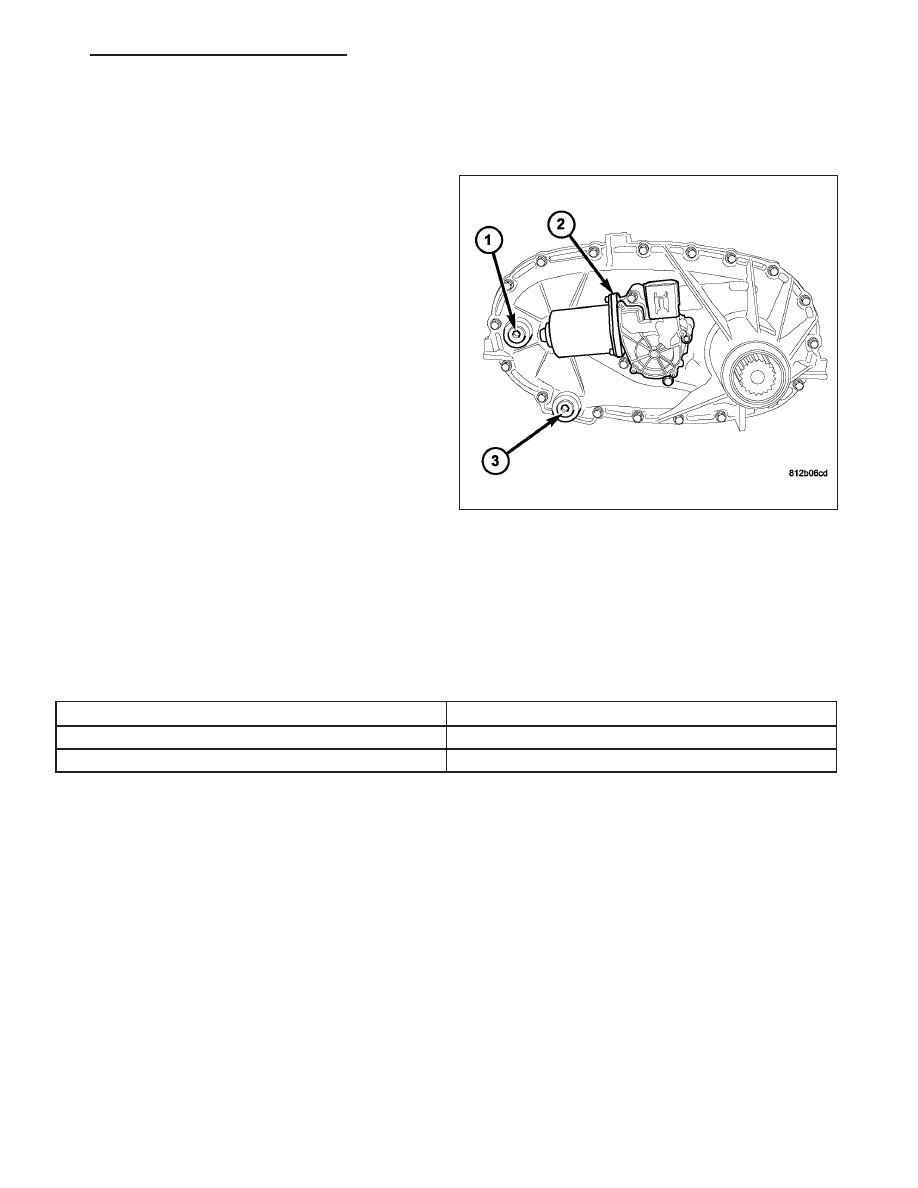
SENSOR-MODE
DESCRIPTION
The transfer case mode sensor (2) provides the Front
Control Module (FCM) feedback about the position of
the transfer case. The sensor consists of a linear ana-
log position sensor that converts the motor output
shaft position into a DC signal. The sensor may rotate
a full 360 degrees for both the NV144 and the NV244
GENII. The operating envelope or sector rotation is -5
to 180 degrees for the NV144 and -40 to 20 degrees
for the NV244 GENII. The FCM must supply 5VDC
(+/- 0.5v) to the sensor whenever the FCM is not in
sleep mode and monitor the shift motor position. The
sensor position is monitored when the ignition is in the
RUN position and for 10 seconds after the ignition is
shifted to the OFF position. The sensor is mechani-
cally linked to the shaft of the cam which allows the
transfer case to shift. The mode sensor will draw less
than 20 mA of current during operation.
OPERATION
During normal vehicle operation, the Front Control Module (FCM) monitors the mode sensor outputs at least every
2 milliseconds when the shift motor is stationary or active.
Refer to SHAFT ANGLE vs. TRANSFER CASE POSITION for the relative angles of the transfer case shift sector
versus the interpreted transfer case gear operating mode.
SHAFT ANGLE vs. TRANSFER CASE POSITION
Shaft Angle (Degrees)
Transfer Case Position
0
AWD
-20
4LOCK
NOTE: All the parameter voltages referred to in the following information are calibrated items in the con-
troller software and are subject to change.
NOTE: For a further explanation of Phase 1 through 3 shifting, (Refer to 8 - ELECTRICAL/ELECTRONIC
CONTROL MODULES/TRANSFER CASE CONTROL MODULE - OPERATION).
The following information describes the different mode sensor positions:
•
4LOCK TARGET REGION - The position shall be considered 4LOCK if the voltage is greater than or equal to
encoder_4LOCK_min Volts and it is also less than or equal to encoder_4LOCK_max Volts.
•
AWD TARGET REGION - The position shall be considered AWD if the voltage is greater than or equal to
encoder_AWD_min Volts and it is also less than or equal to encoder_AWD_max Volts.
•
AWD SHIFT LIMIT - During Phase 2 and Phase 3 shifting, shifts may become unidirectional when a voltage is
greater than or equal to encoder_AWD_min Volts has been reached.
The mode sensor position will be considered invalid by the FCM if the voltage is greater than or equal to encoder-
_High_Range_Limit Volts or if it is less than or equal to encoder_Low_Range_Limit Volts.
If FCM looses the encoder signal in a NV144 transfer case during a shift, the FCM will respond with a shift back in
the opposite direction of travel to first attempt to find the encoder signal. If the signal is not found, the FCM will drive
motor in AWD direction for 1 second.
HB
TRANSFER CASE - NV144 - SERVICE INFORMATION
21 - 829