Dodge Durango (HB). Manual - part 1042


  Index      Dodge     Dodge Durango (HB) - service repair manual 2005 year


Search            


Content   ..  1040  1041  1042  1043   ..


Dodge Durango (HB). Manual - part 1042


OIL

STANDARD PROCEDURE

ENGINE OIL SERVICE

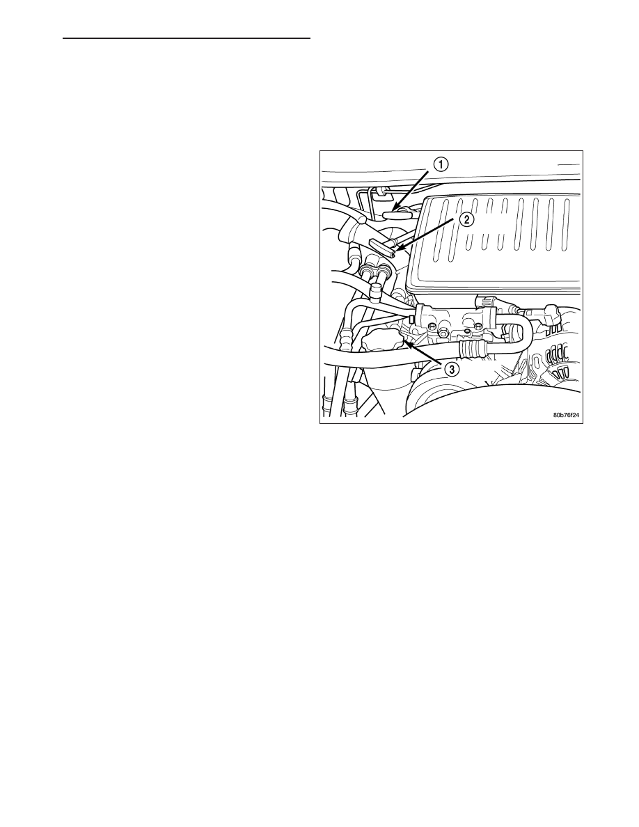
The engine oil level indicator (2) is located at the right
rear of the engine on the 3.7L engines..

CRANKCASE OIL LEVEL INSPECTION

CAUTION: Do not overfill crankcase with engine oil, pressure loss or oil foaming can result.

Inspect engine oil level approximately every 800 kilometers (500 miles). Unless the engine has exhibited loss of oil
pressure, run the engine for about five minutes before checking oil level. Checking engine oil level on a cold engine
is not accurate.

To ensure proper lubrication of an engine, the engine oil must be maintained at an acceptable level. The acceptable
levels are indicated between the ADD and SAFE marks on the engine oil dipstick.

1. Position vehicle on level surface.

2. With engine OFF, allow approximately ten minutes for oil to settle to bottom of crankcase, remove engine oil

dipstick.

3. Wipe dipstick clean.

4. Install dipstick and verify it is seated in the tube.

5. Remove dipstick, with handle held above the tip, take oil level reading.

6. Add oil only if level is below the ADD mark on dipstick.

ENGINE OIL CHANGE

Change engine oil at mileage and time intervals described in Maintenance Schedules.

Run engine until achieving normal operating temperature.

1. Position the vehicle on a level surface and turn engine off.

2. Hoist and support vehicle on safety stands.

3. Remove oil fill cap.

4. Place a suitable drain pan under crankcase drain.

HB

ENGINE - 3.7L SERVICE INFORMATION

9 - 1167

5. Remove drain plug from crankcase and allow oil to drain into pan. Inspect drain plug threads for stretching or

other damage. Replace drain plug if damaged.

6. Install drain plug in crankcase.

7. Lower vehicle and fill crankcase with specified type and amount of engine oil described in this section.

8. Install oil fill cap.

9. Start engine and inspect for leaks.

10. Stop engine and inspect oil level.

USED ENGINE OIL DISPOSAL

Care should be exercised when disposing used engine oil after it has been drained from a vehicle engine. Refer to
the WARNING at beginning of this section.

MANIFOLD-INTAKE

DESCRIPTION

The intake manifold (2) is made of a composite mate-
rial and features 300 mm (11.811 in.) long runners
which maximizes low end torque. The intake manifold
(2) uses single plane sealing which consist of six indi-
vidual press in place port gaskets to prevent leaks.
The throttle body (1) attaches directly to the intake
manifold (2). Eight studs and two bolts are used to
fasten the intake to the head.

DIAGNOSIS AND TESTING

INTAKE MANIFOLD LEAKS

An intake manifold air leak is characterized by lower than normal manifold vacuum. Also, one or more cylinders may
not be functioning.

WARNING: USE EXTREME CAUTION WHEN THE ENGINE IS OPERATING. DO NOT STAND IN A DIRECT LINE
WITH THE FAN. DO NOT PUT YOUR HANDS NEAR THE PULLEYS, BELTS OR THE FAN. DO NOT WEAR
LOOSE CLOTHING.

9 - 1168

ENGINE - 3.7L SERVICE INFORMATION

HB

1. Start the engine.

2. Spray a small stream of water (spray bottle) at the suspected leak area.

3. If engine RPM’S change, the area of the suspected leak has been found.

4. Repair as required.

REMOVAL

1. Disconnect negative cable from battery.

2. Remove resonator assembly and air inlet hose.

3. Disconnect throttle and speed control cables.

4. Disconnect electrical connectors for the following components: Refer to FUEL SYSTEM for component locations.

Manifold Absolute Pressure (MAP) Sensor

Intake Air Temperature (IAT) Sensor

Throttle Position (TPS) Sensor

Coolant Temperature (CTS) Sensor

Idle Air Control (IAC) Motor

5. Disconnect vapor purge hose, brake booster hose, speed control servo hose, positive crankcase ventilation

(PCV) hose.

6. Disconnect generator electrical connections.

7. Disconnect air conditioning compressor electrical connections.

8. Disconnect left and right radio suppressor straps.

9. Disconnect and remove ignition coil towers.

10. Remove top oil dipstick tube retaining bolt and ground strap.

11. Bleed fuel system (Refer to 14 - FUEL SYSTEM/FUEL DELIVERY - STANDARD PROCEDURE).

12. Remove fuel rail.

13. Remove throttle body assembly and mounting bracket.

14. Drain cooling system below coolant temperature level (Refer to 7 - COOLING - STANDARD PROCEDURE).

15. Remove the heater hoses from the engine front cover and the heater core.

16. Unclip and remove heater hoses and tubes from intake manifold.

17. Remove coolant temperature sensor (Refer to 7 - COOLING/ENGINE/ENGINE COOLANT TEMP SENSOR -

REMOVAL) .

18. Remove intake manifold retaining fasteners in reverse order of tightening sequence.

19. Remove intake manifold.

HB

ENGINE - 3.7L SERVICE INFORMATION

9 - 1169

INSTALLATION

1. Install intake manifold gaskets.

2. Install intake manifold.

3. Install intake manifold retaining bolts and tighten in

sequence shown in to 12 N·m (105 in. lbs.).

4. Install left and right radio suppressor straps.

5. Install throttle body assembly.

6. Connect throttle cable and speed control cable to

throttle body.

7. Install fuel rail.

8. Install ignition coil towers.

9. Position and install heater hoses and tubes onto

intake manifold.

10. Install the heater hoses to the heater core and

engine front cover.

11. Connect electrical connectors for the following

components:

Manifold Absolute Pressure (MAP) Sensor

Intake Air Temperature (IAT) Sensor

Throttle Position (TPS) Sensor

Coolant Temperature (CTS) Sensor

Idle Air Control (IAC) Motor

Ignition coil towers

Fuel injectors

12. Install top oil dipstick tube retaining bolt and ground strap.

13. Connect generator electrical connections.

14. Connect Vapor purge hose, Brake booster hose, Speed control servo hose, Positive crankcase ventilation

(PCV) hose.

15. Fill cooling system (Refer to 7 - COOLING - STANDARD PROCEDURE).

16. Install resonator assembly and air inlet hose.

17. Connect negative cable to battery.

9 - 1170

ENGINE - 3.7L SERVICE INFORMATION

HB


Content   ..  1040  1041  1042  1043   ..