Dodge Durango (DN). Manual - part 430
CAUTION: Care should be taken not to damage
camshaft target wheel. Do not hold target wheel
while loosening or tightening camshaft sprocket.
Do not place the target wheel near a magnetic
source of any kind. A damaged or magnetized tar-
get wheel could cause a vehicle no start condition.
CAUTION: Do not forcefully rotate the camshafts or
crankshaft independently of each other. Damaging
intake valve to piston contact will occur. Ensure
negative battery cable is disconnected to guard
against accidental starter engagement.
(13) Remove left and right camshaft sprocket bolts.
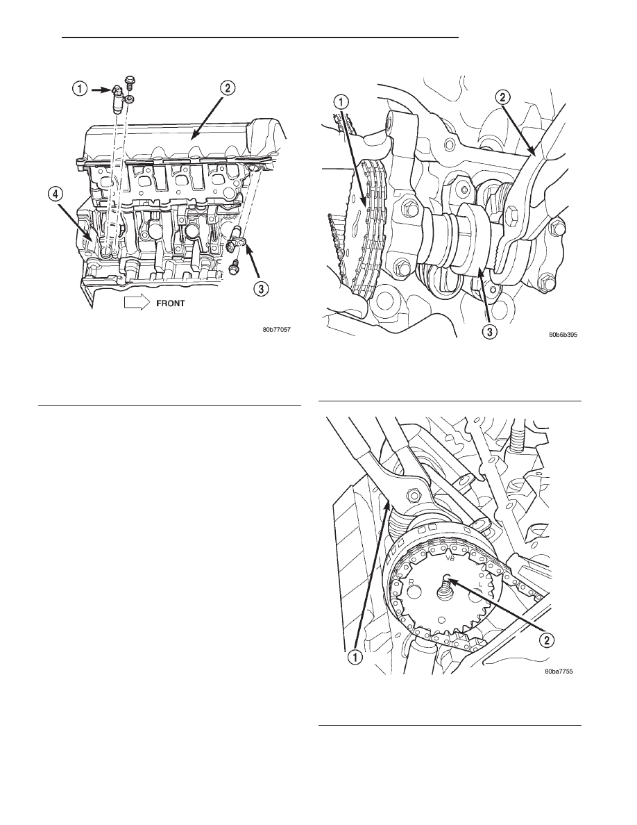
(14) While holding the left camshaft steel tube
with adjustable pliers, (Fig. 80) remove the left cam-
shaft sprocket. Slowly rotate the camshaft approxi-
mately 15 degrees clockwise to a neutral position.
(15) While holding the right camshaft steel tube
with adjustable pliers, (Fig. 81) remove the right
camshaft
sprocket.
Slowly
rotate
the
camshaft
approximately 45 degrees counterclockwise to a neu-
tral position.
(16) Remove idler sprocket assembly bolt.
(17) Slide the idler sprocket assembly and crank
sprocket forward simultaneously to remove the pri-
mary and secondary chains.
(18) Remove both pivoting tensioner arms and
chain guides.
(19) Remove chain tensioner.
Fig. 79 Camshaft Position Sensor—Removal
1 – CRANKSHAFT POSITION SENSOR
2 – CYLINDER HEAD COVER
3 – CAMSHAFT POSITION SENSOR
4 – RIGHT SIDE CYLINDER BLOCK
Fig. 80 Camshaft Rotation—Left Side
1 – CAMSHAFT SPROCKET AND CHAIN
2 – ADJUSTABLE PLIERS
3 – CAMSHAFT
Fig. 81 Camshaft Rotation—Right Side
1 – ADJUSTABLE PLIERS
2 – CAMSHAFT DOWEL
DN
4.7L ENGINE
9 - 51
REMOVAL AND INSTALLATION (Continued)