Dodge Durango (DN). Manual - part 428
(21) Remove the cylinder head retaining bolts.
(22) Remove the cylinder head and gasket. Discard
the gasket.
CAUTION: Do not lay the cylinder head on its gas-
ket sealing surface, due to the design of the cylin-
der head gasket any distortion to the cylinder head
sealing surface may prevent the gasket from prop-
erly sealing resulting in leaks.
INSTALLATION
NOTE: The cylinder head bolts are tightened using
a torque plus angle procedure. The bolts must be
examined BEFORE reuse. If the threads are necked
down the bolts should be replaced.
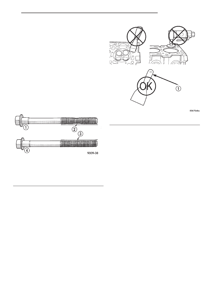
Necking can be checked by holding a straight edge
against the threads. If all the threads do not contact
the scale, the bolt should be replaced (Fig. 61).
CAUTION: When cleaning cylinder head and cylin-
der block surfaces, DO NOT use a metal scraper
because the surfaces could be cut or ground. Use
only a wooden or plastic scraper.
(1) Clean the cylinder head and cylinder block
mating surfaces (Fig. 62).
(2) Position the new cylinder head gasket on the
locating dowels.
CAUTION: When installing cylinder head, use care
not damage the tensioner arm or the guide arm.
(3) Position the cylinder head onto the cylinder
block. Make sure the cylinder head seats fully over
the locating dowels.
NOTE: The four smaller cylinder head mounting
bolts require sealant to be added to them before
installing. Failure to do so may cause leaks.
(4) Lubricate the cylinder head bolt threads with
clean engine oil and install the ten M11 bolts.
(5) Coat the four M8 cylinder head bolts with
Mopar
t Lock and Seal Adhesive then install the
bolts.
NOTE: The cylinder head bolts are tightened using
an angle torque procedure, however, the bolts are
not a torque-to-yield design.
(6) Tighten the bolts in sequence (Fig. 63) using
the following steps and torque values:
• Step 1: Tighten bolts 1–10, 20 N·m (15 ft. lbs.).
• Step 2: Tighten bolts 1–10, 47 N·m (35 ft. lbs.).
Tighten bolts 11–14, 25 N·m (18 ft. lbs.).
• Step 3: Tighten bolts 1–10, 90 degrees. Tighten
bolts 11–14, 30 N·m (22 ft. lbs.).
(7) Position the secondary chain onto the camshaft
drive gear, making sure one marked chain link is on
either side of the V8 mark on the gear and position
the gear onto the camshaft.
(8) Install the camshaft drive gear retaining bolt.
(9) Install the left side secondary chain guide.
(10) Install the cylinder head access plug.
(11) Re-set and Install the left side secondary
chain tensioner.
(12) Remove Special Tool 8515.
(13) Install the timing chain cover.
Fig. 61 Checking Cylinder Head Bolts for Stretching
(Necking)
1 – STRETCHED BOLT
2 – THREADS ARE NOT STRAIGHT ON LINE
3 – THREADS ARE STRAIGHT ON LINE
4 – UNSTRETCHED BOLT
Fig. 62 Proper Tool Usage for Surface Preparation
1 – PLASTIC/WOOD SCRAPER
DN
4.7L ENGINE
9 - 43
REMOVAL AND INSTALLATION (Continued)