Dodge Durango (DN). Manual - part 57
 

  Index      Dodge     Dodge Durango (DN) - service repair manual 2000 year


Search            


Content   ..  55  56  57  58   ..


Dodge Durango (DN). Manual - part 57


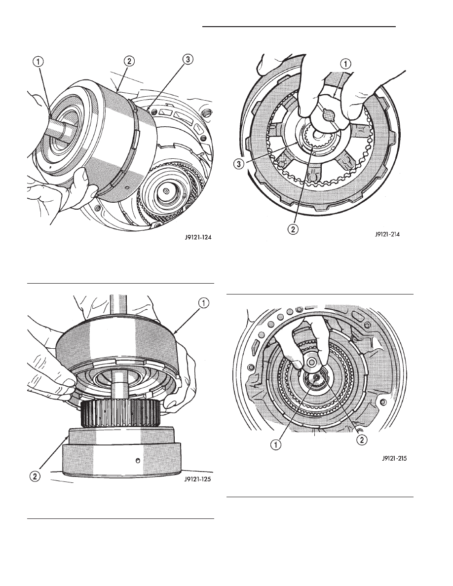
Fig. 155 Removing Front/Rear Clutch Assemblies

1 – INPUT SHAFT
2 – FRONT CLUTCH
3 – REAR CLUTCH

Fig. 156 Separating Front/Rear Clutch Assemblies

1 – FRONT CLUTCH
2 – REAR CLUTCH

Fig. 157 Removing Intermediate Shaft Thrust

Washer

1 – INTERMEDIATE SHAFT THRUST WASHER
2 – INPUT SHAFT
3 – REAR CLUTCH RETAINER HUB

Fig. 158 Removing Intermediate Shaft Thrust Plate

1 – INTERMEDIATE SHAFT HUB
2 – INTERMEDIATE SHAFT THRUST PLATE

21 - 94

42/44RE AUTOMATIC TRANSMISSION

DN

DISASSEMBLY AND ASSEMBLY (Continued)

(27) Remove planetary geartrain as assembly (Fig.

160). Support geartrain with both hands during
removal. Do not allow machined surfaces on interme-
diate shaft or overdrive piston retainer to become
nicked or scratched.

(28) If overdrive unit is not to be serviced, install

Alignment Shaft 6227-2 into the overdrive unit to
prevent misalignment of the overdrive clutches dur-
ing service of main transmission components.

(29) Loosen rear band adjusting screw 4-5 turns.
(30) Remove low-reverse drum snap ring (Fig.

161).

(31) Remove low-reverse drum and reverse band.
(32) Remove overrunning clutch roller and spring

assembly as a unit (Fig. 162).

(33) Compress front servo rod guide about 1/8 inch

with Valve Spring Compressor C-3422-B (Fig. 163).

(34) Remove front servo rod guide snap ring.

Exercise caution when removing snap ring.
Servo bore can be scratched or nicked if care is
not exercised.

(35) Remove compressor tools and remove front

servo rod guide, spring and servo piston.

(36) Compress rear servo spring retainer about

1/16 inch with Valve Spring Compressor C-3422-B
(Fig. 164).

(37) Remove rear servo spring retainer snap ring.

Then remove compressor tools and remove rear servo
spring and piston.

(38) Inspect transmission components.

Fig. 160 Removing Planetary Geartrain And

Intermediate Shaft Assembly

1 – PLANETARY GEARTRAIN AND INTERMEDIATE SHAFT

ASSEMBLY

Fig. 159 Front Band Removal/Installation

1 – DRIVING SHELL
2 – FRONT BAND

Fig. 161 Removing Low-Reverse Drum Snap Ring

1 – LOW-REVERSE DRUM
2 – HUB OF OVERDRIVE PISTON RETAINER
3 – LOW-REVERSE DRUM SNAP RING

DN

42/44RE AUTOMATIC TRANSMISSION

21 - 95

DISASSEMBLY AND ASSEMBLY (Continued)

NOTE: TO SERVICE THE OVERRUNNING CLUTCH
CAM OR OVERDRIVE PISTON RETAINER, REFER
TO OVERRUNNING CLUTCH CAM SERVICE IN THIS
SECTION.

ASSEMBLY

Do not allow dirt, grease, or foreign material to

enter the case or transmission components during
assembly. Keep the transmission case and compo-
nents clean. Also make sure the tools and workbench
area used for assembly operations are equally clean.

Shop towels used for wiping off tools and hands

must be made from lint free material. Lint will stick
to transmission parts and could interfere with valve
operation, or even restrict fluid passages.

Lubricate

the

transmission

components

with

Mopar

t transmission fluid during reassembly. Use

Mopar

t Door Ease, or Ru-Glyde on seals and O-rings

to ease installation.

Petroleum jelly can also be used to hold thrust

washers, thrust plates and gaskets in position during
assembly. However, do not use chassis grease, bear-
ing grease, white grease, or similar lubricants on any
transmission part. These types of lubricants can
eventually block or restrict fluid passages and inter-
fere with valve operation. Use petroleum jelly only.

Do not force parts into place. The transmission

components and subassemblies are easily installed by
hand when properly aligned.

If a part seems extremely difficult to install, it is

either misaligned or incorrectly assembled. Also ver-
ify that thrust washers, thrust plates and seal rings
are correctly positioned before assembly. These parts
can interfere with proper assembly if mis-positioned.

The planetary geartrain, front/rear clutch assem-

blies and oil pump are all much easier to install
when the transmission case is upright.

(1) Install rear servo piston, spring and retainer

(Fig. 165). Install spring on top of servo piston and
install retainer on top of spring.

Fig. 162 Overrunning Clutch Assembly Removal

1 – OVERRUNNING CLUTCH CAM
2 – REAR BAND REACTION PIN
3 – OVERRUNNING CLUTCH ASSEMBLY

Fig. 163 Compressing Front Servo Rod Guide

1 – SPRING COMPRESSOR TOOL C-3422-B
2 – ROD GUIDE SNAP RING

Fig. 164 Compressing Rear Servo Spring

1 – FRONT SERVO SNAP RING
2 – REAR SERVO SNAP RING
3 – SPECIAL TOOL

21 - 96

42/44RE AUTOMATIC TRANSMISSION

DN

DISASSEMBLY AND ASSEMBLY (Continued)

(2) Install

front

servo

piston

assembly,

servo

spring and rod guide (Fig. 166).

(3) Compress front/rear servo springs with Valve

Spring Compressor C-3422-B and install each servo
snap ring (Fig. 167).

(4) Lubricate clutch cam rollers with transmission

fluid.

(5) Install rear band in case (Fig. 168). Be sure

twin lugs on band are seated against reaction pin.

(6) Install low-reverse drum and check overrun-

ning clutch operation as follows:

(a) Lubricate overrunning clutch race (on drum

hub) with transmission fluid.

(b) Guide drum through rear band.
(c) Tilt drum slightly and start race (on drum

hub) into overrunning clutch rollers.

(d) Press drum rearward and turn it in clock-

wise direction until drum seats in overrunning
clutch (Fig. 169).

Fig. 165 Rear Servo Components

1 – SERVO PISTON
2 – PISTON SPRING
3 – SNAP RING
4 – RETAINER
5 – PISTON SEAL

Fig. 166 Front Servo Components

1 – PISTON SEAL RINGS
2 – SERVO PISTON
3 – SNAP RING
4 – ROD GUIDE
5 – SPRING
6 – ROD

Fig. 167 Compressing Front/Rear Servo Springs

1 – SPRING COMPRESSOR TOOL C-3422-B
2 – ROD GUIDE SNAP RING

Fig. 168 Rear Band Installation

1 – REAR BAND

DN

42/44RE AUTOMATIC TRANSMISSION

21 - 97

DISASSEMBLY AND ASSEMBLY (Continued)


Content   ..  55  56  57  58   ..