Dodge Durango (DN). Manual - part 41
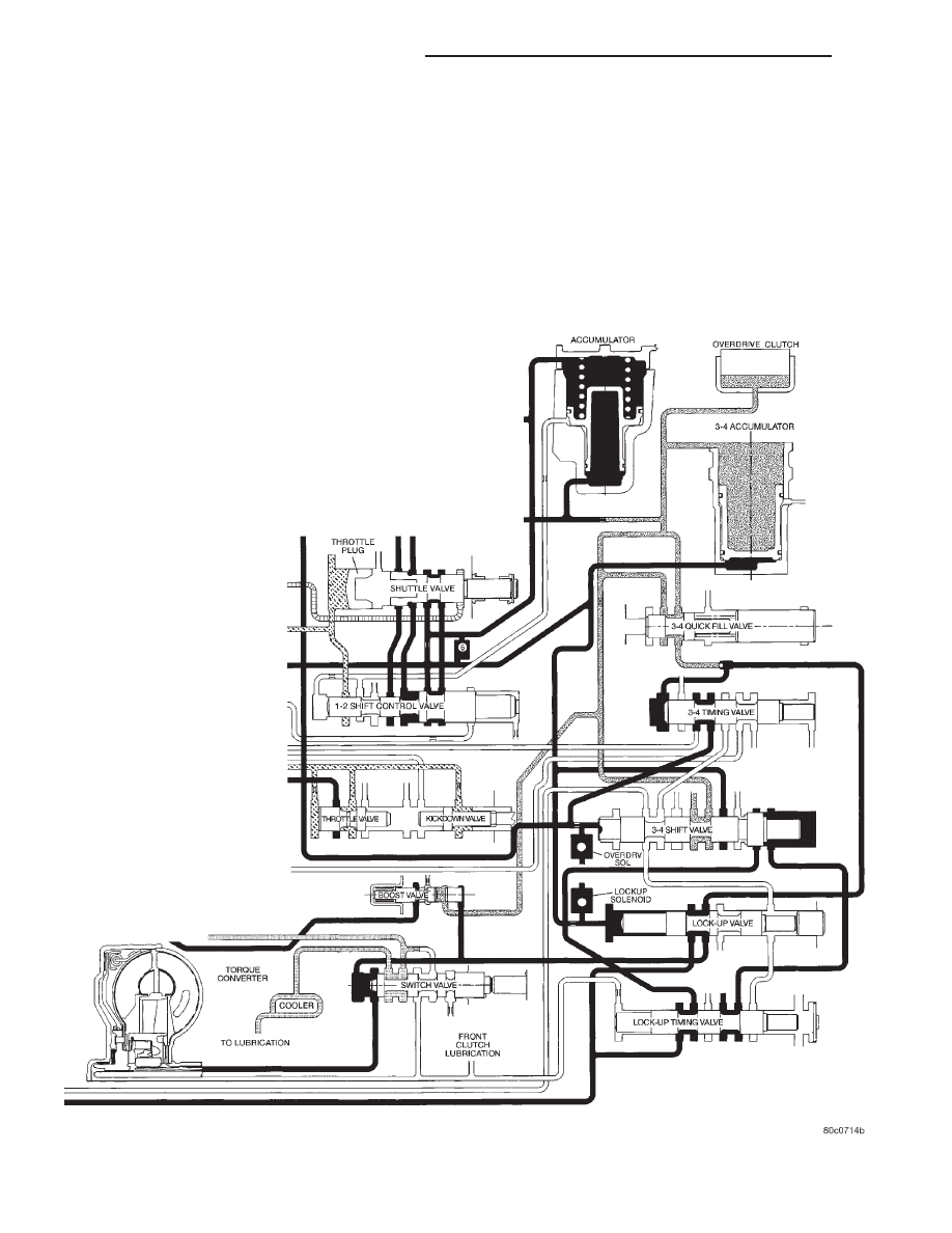
switch valve, forcing the valve to the right. The
switch valve now vents oil from the front of the pis-
ton in the torque converter, and supplies line pres-
sure to the (rear) apply side of the torque converter
piston. This pressure differential causes the piston to
apply against the friction material, cutting off any
further flow of line pressure oil. After the switch
valve is shuttled right allowing line pressure to
engage
the
TCC,
torque
converter
pressure
is
directed past the switch valve into the transmission
cooler and lubrication circuits.
MANUAL VALVE
The manual valve (Fig. 43) is a relay valve. The
purpose of the manual valve is to direct fluid to the
correct circuit needed for a specific gear or driving
range. The manual valve, as the name implies, is
manually operated by the driver with a lever located
on the side of the valve body. The valve is connected
mechanically by either a cable or linkage to the gear-
shift mechanism. The valve is held in each of its
positions by a spring–loaded roller or ball that
engages the “roostercomb” of the manual valve.
Fig. 42 Switch Valve-Torque Converter Locked
21 - 30
42/44RE AUTOMATIC TRANSMISSION
DN
DESCRIPTION AND OPERATION (Continued)