Dodge Durango (DN). Manual - part 39
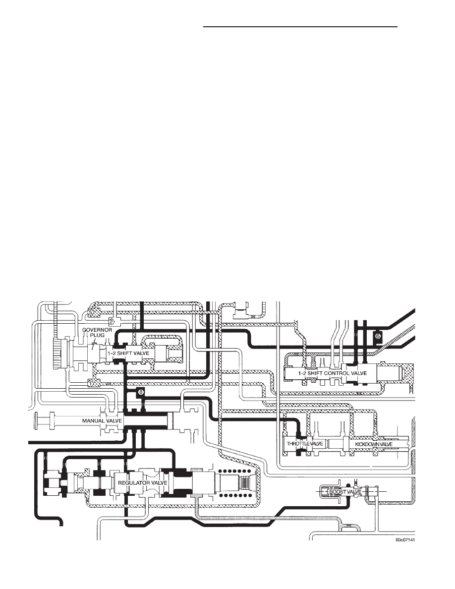
KICKDOWN VALVE
When the throttle valve is as far over to the left as
it can go, the maximum line pressure possible will
enter the throttle pressure circuit. In this case, throt-
tle pressure will equal line pressure. With the kick-
down valve (Fig. 26) pushed into the bore as far as it
will go, fluid initially flows through the annular
groove of the 2–3 shift valve (which will be in the
direct drive position to the right).
After passing the annular groove, the fluid is
routed to the spring end of the 2–3 shift valve. Fluid
pressure reacting on the area of land #1 overcomes
governor pressure, downshifting the 2–3 shift valve
into the kickdown, or second gear stage of operation.
The valve is held in the kickdown position by throttle
pressure routed from a seated check ball (#2). Again,
if vehicle speed is low enough, throttle pressure will
also push the 1–2 shift valve left to seat its governor
plug, and downshift to drive breakaway.
KICKDOWN LIMIT VALVE
The purpose of the limit valve is to prevent a 3–2
downshift at higher speeds when a part–throttle
downshift is not desirable. At these higher speeds
only a full throttle 3–2 downshift will occur. At low
road speeds (Fig. 27) the limit valve does not come
into play and does not affect the downshifts. As the
vehicle’s speed increases (Fig. 28), the governor pres-
sure also increases. The increased governor pressure
acts on the reaction area of the bottom land of the
limit valve overcoming the spring force trying to push
the valve toward the bottom of its bore. This pushes
the valve upward against the spring and bottoms the
valve against the top of the housing. With the valve
bottomed against the housing, the throttle pressure
supplied to the valve will be closed off by the bottom
land of the limit valve. When the supply of throttle
pressure has been shut off, the 3–2 part throttle down-
shift plug becomes inoperative, because no pressure is
acting on its reaction area.
1–2 SHIFT VALVE
The 1–2 shift valve assembly (Fig. 29), or mecha-
nism, consists of: the 1–2 shift valve, governor plug,
and a spring on the end of the valve. After the manual
valve has been placed into a forward gear range, line
pressure is directed to the 1–2 shift valve. As the
throttle is depressed, throttle pressure is applied to
the right side of the 1–2 shift valve assembly. With
throttle pressure applied to the right side of the valve,
there is now both spring pressure and throttle pres-
sure acting on the valve, holding it against the gover-
nor plug. As the vehicle begins to move and build
Fig. 26 Kickdown Valve–Wide Open Throttle
21 - 22
42/44RE AUTOMATIC TRANSMISSION
DN
DESCRIPTION AND OPERATION (Continued)