Dodge Durango (DN). Manual - part 37
TORQUE CONVERTER CLUTCH (TCC)
In a standard torque converter, the impeller and
turbine are rotating at about the same speed and the
stator is freewheeling, providing no torque multipli-
cation. By applying the turbine’s piston to the front
cover’s friction material, a total converter engage-
ment can be obtained. The result of this engagement
is a direct 1:1 mechanical link between the engine
and the transmission.
Converter clutch engagement in third or fourth gear
range is controlled by sensor inputs to the powertrain
control module. Inputs that determine clutch engage-
ment are: coolant temperature, engine rpm, vehicle
speed, throttle position, and manifold vacuum. The
torque converter clutch is engaged by the clutch sole-
noid on the valve body. The clutch can be engaged in
third and fourth gear ranges depending on overdrive
control switch position. If the overdrive control switch is
in the normal ON position, the clutch will engage after
the shift to fourth gear, and above approximately 72
km/h (45 mph). If the control switch is in the OFF posi-
tion, the clutch will engage after the shift to third gear,
at approximately 56 km/h (35 mph) at light throttle.
OIL PUMP
DESCRIPTION
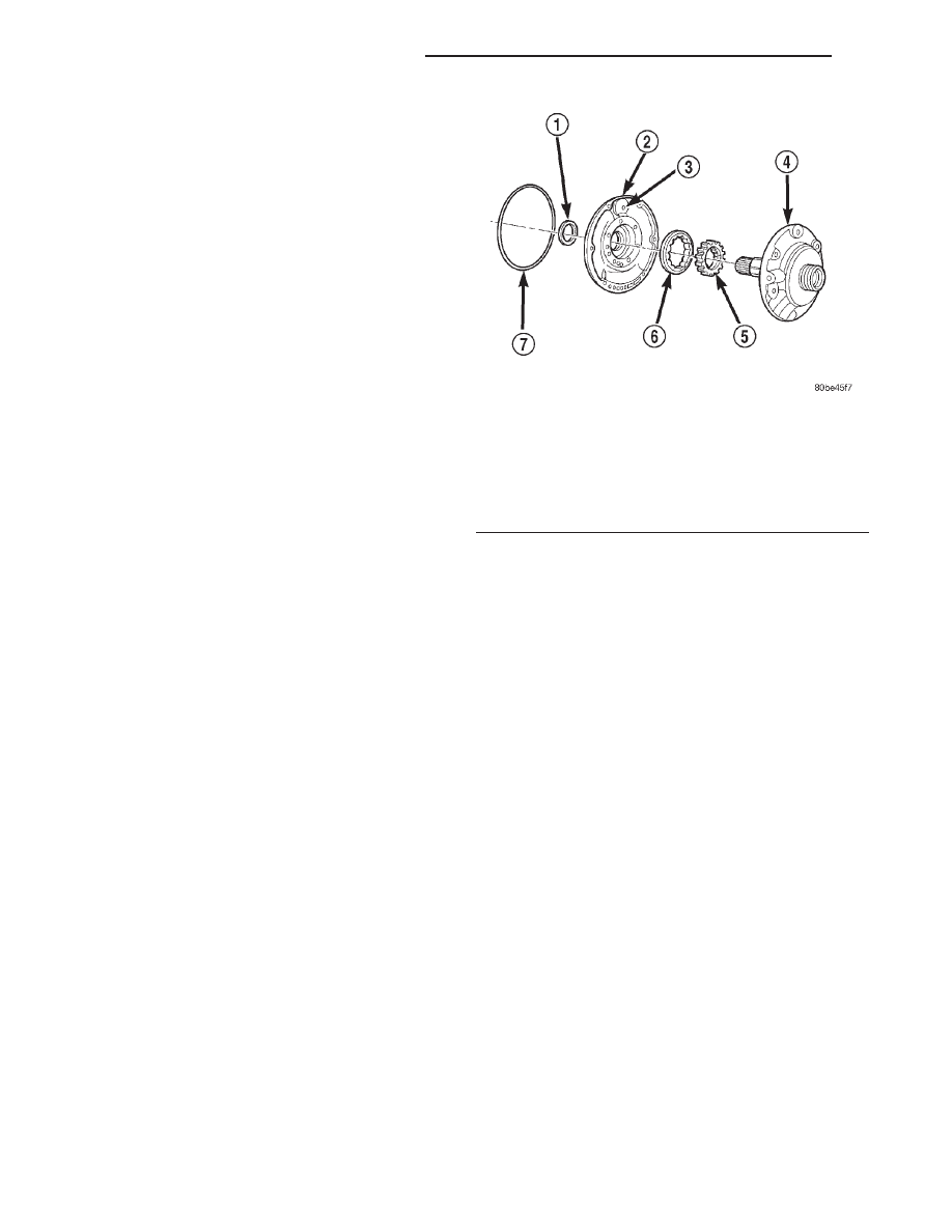
The oil pump (Fig. 17) is located in the pump hous-
ing inside the bell housing of the transmission case.
The oil pump consists of an inner and outer gear, a
housing, and a cover that also serves as the reaction
shaft support.
OPERATION
As the torque converter rotates, the converter hub
rotates the inner and outer gears. As the gears
rotate,
the
clearance
between
the
gear
teeth
increases in the crescent area, and creates a suction
at the inlet side of the pump. This suction draws
fluid through the pump inlet from the oil pan. As the
clearance between the gear teeth in the crescent area
decreases, it forces pressurized fluid into the pump
outlet and to the valve body.
VALVE BODY
DESCRIPTION
The valve body consists of a cast aluminum valve
body, a separator plate, and transfer plate. The valve
body contains valves and check balls that control
fluid delivery to the torque converter clutch, bands,
and frictional clutches. The valve body contains the
following components (Fig. 18), (Fig. 19), (Fig. 20),
and (Fig. 21):
• Regulator valve
• Regulator valve throttle pressure plug
• Line pressure plug and sleeve
• Kickdown valve
• Kickdown limit valve
• 1–2 shift valve
• 1–2 control valve
• 2–3 shift valve
• 2–3 governor plug
• 3–4 shift valve
• 3–4 timing valve
• 3–4 quick fill valve
• 3–4 accumulator
• Throttle valve
• Throttle pressure plug
• Switch valve
• Manual valve
• Converter clutch lock-up valve
• Converter clutch lock-up timing Valve
• Shuttle valve
• Shuttle valve throttle plug
• Boost Valve
• 10 check balls
By adjusting the spring pressure acting on the reg-
ulator valve, transmission line pressure can be
adjusted.
Fig. 17 Oil Pump Assembly
1 – OIL SEAL
2 – OIL PUMP BODY
3 – VENT
4 – REACTION SHAFT SUPPORT
5 – INNER ROTOR
6 – OUTER ROTOR
7 – “O” RING
21 - 14
42/44RE AUTOMATIC TRANSMISSION
DN
DESCRIPTION AND OPERATION (Continued)