Dodge Durango (DN). Manual - part 32
INSTALLATION
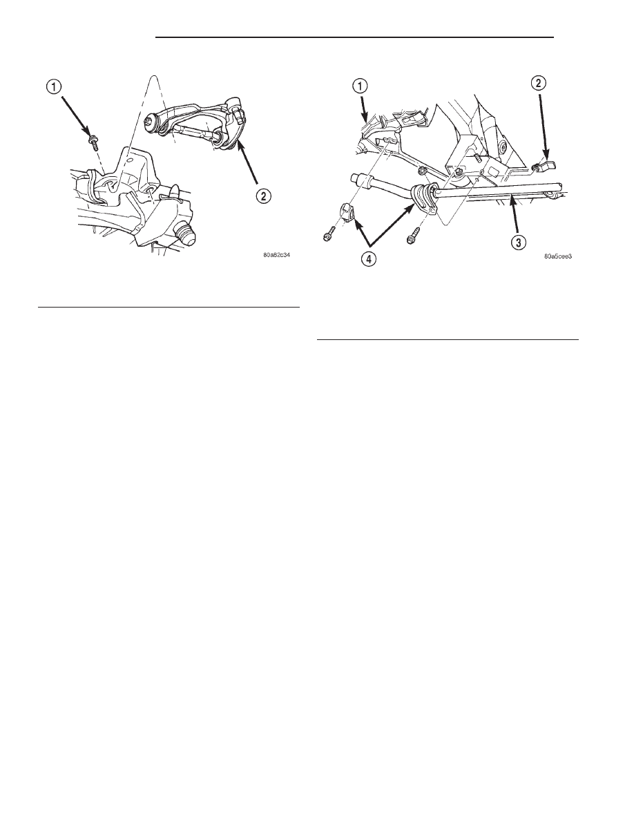
(1) Position suspension arm pivot bar on mounting
bracket. Install bolts and tighten (temporarily) to 136
N·m (100 ft. lbs.).
(2) Insert
ball
joint
in
steering
knuckle
and
tighten ball joint nut to 81 N·m (60 ft. lbs.) then
install a new cotter pin.
(3) Install shock absorber.
NOTE: Upper shock nut must be replaced or use
Mopar Lock ’N Seal or Loctite
T
242 on existing nut.
(4) Remove hydraulic jack.
(5) Attach brake hose brackets to suspension arm,
refer to Group 5 Brakes.
(6) Tighten upper suspension arm pivot bolts to
204 N·m (150 ft. lbs.).
(7) Install the wheel and tire assembly.
(8) Remove support and lower vehicle.
(9) Align front suspension.
STABILIZER BAR
NOTE: To service the stabilizer bar the vehicle
must be on a drive on hoist. The vehicle suspen-
sion must be at curb height for stabilizer bar instal-
lation.
REMOVAL
(1) Remove the stabilizer bar retainer bolts from
the lower suspension arms (Fig. 13) and remove the
retainers.
(2) Remove the stabilizer bar retainer nuts, bolts
and retainers from the frame crossmember (Fig. 13)
and remove the bar.
(3) If necessary, remove the bushings from the sta-
bilizer bar.
INSTALLATION
(1) If removed, install the bushings on the stabi-
lizer bar.
(2) Position the stabilizer bar on the frame cross-
member brackets and install the retainers and nuts
and bolts finger-tight (Fig. 13).
NOTE: Check the alignment of the bar to ensure
there is no interference with the either frame rail or
chassis component. Spacing should be equal on
both sides.
(3) Install the stabilizer bar to the lower suspen-
sion arm.
(4) Install the retainers and bolts to the lower sus-
pension arm and tighten to 34 N·m (25 ft. lbs.).
(5) Tighten the frame retainer nuts to 190 N·m
(140 ft. lbs.).
(6) Tighten the frame retainer bolts to 108 N·m
(80 ft. lbs.).
HUB/BEARING
REMOVAL
(1) Raise and support vehicle.
(2) Remove wheel and tire assembly.
(3) Remove axle nut.
(4) Remove ABS wheel speed sensor if equipped,
refer to Group 5 Brakes.
(5) Remove the brake caliper and rotor, refer to
Group 5 Brakes.
(6) Remove hub/bearing mounting bolts from the
steering knuckle (Fig. 14).
Fig. 12 Upper Suspension Arm
1 – PIVOT BAR BOLT
2 – UPPER SUSPENSION ARM
Fig. 13 Stabilizer Bar
1 – LOWER SUSPENSION ARM
2 – FLAG NUT
3 – STABILIZER BAR
4 – RETAINER
2 - 20
SUSPENSION
DN
REMOVAL AND INSTALLATION (Continued)