Dodge Durango (DN). Manual - part 31
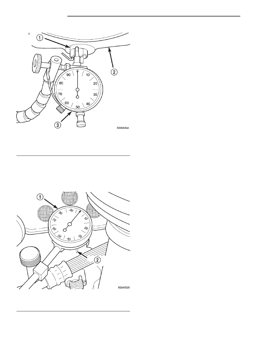
(2) Mount a dial indicator solidly on the upper sus-
pension arm.
(3) Position the indicator plunger against the back
side of the upper ball joint boss of the steering
knuckle (Fig. 3).
(4) Grasp the top of the tire and pull outward,
then zero the dial indicator.
(5) Grasp the top of the tire and push inward and
record the dial indicator reading.
(6) If lateral movement is greater than 1.52 mm
(0.060 in.), replace upper suspension arm.
SHOCK DIAGNOSIS
A knocking or rattling noise from a shock absorber
may be caused by movement between mounting
bushings and metal brackets or attaching compo-
nents. These noises can usually be stopped by tight-
ening the attaching nuts. If the noise persists,
inspect for damaged and worn bushings, and attach-
ing components. Repair as necessary if any of these
conditions exist.
A squeaking noise from the shock absorber may be
caused by the hydraulic valving and may be intermit-
tent. This condition is not repairable and the shock
absorber must be replaced.
The shock absorbers are not refillable or adjust-
able. If a malfunction occurs, the shock absorber
must be replaced. To test a shock absorber, hold it in
an upright position and force the piston in and out of
the cylinder four or five times. The action throughout
each stroke should be smooth and even.
The shock absorber bushings do not require any
type of lubrication. Do not attempt to stop bushing
noise by lubricating them. Grease and mineral oil-
base lubricants will deteriorate the bushing.
REMOVAL AND INSTALLATION
SHOCK ABSORBER
REMOVAL
(1) Raise and support vehicle.
(2) Remove the upper shock absorber nut, retainer
and grommet (Fig. 4).
(3) Remove the lower bolt and remove the shock
absorber.
INSTALLATION
NOTE: Upper shock nut must be replaced or use
Mopar Lock ’N Seal or Loctite
T
242 on existing nut.
(1) Install the lower retainer (lower retainer is
stamped with a L) and grommet on the shock
absorber stud. Insert the shock absorber through the
frame bracket hole.
(2) Install the lower bolt and tighten the bolt to
108 N·m (80 ft. lbs.).
(3) Install the upper grommet, retainer (upper
retainer is stamped with a U) and new nut or use
Mopar Lock ’N Seal or Loctite
t 242 on existing nut,
on the shock absorber stud. Tighten nut to 26 N·m
(19 ft. lbs.).
Fig. 2 Lower Ball Joint Boss
1 – BALL JOINT BOSS
2 – STEERING KNUCKLE
3 – DIAL INDICATOR
Fig. 3 Upper Ball Joint Boss
1 – DIAL INDICATOR
2 – BALL JOINT BOSS
2 - 16
SUSPENSION
DN
DIAGNOSIS AND TESTING (Continued)