Dodge Durango (DN). Manual - part 25
(5) Remove support and lower vehicle.
(6) Adjust the wheel toe position, Refer to Group 2
Suspension.
RACK & PINION STEERING GEAR - 4x2
REMOVAL
(1) Raise and support the vehicle.
(2) Remove the nuts from the tie rod ends.
(3) Separate tie rod ends from the knuckles with
Puller C-3894-A (Fig. 3).
(4) Remove the power steering lines from the gear.
(5) Remove the lower coupler bolt and slide the
coupler off the gear (Fig. 4).
(6) Remove the mounting bolts from the gear to
the front crossmember and remove the gear (Fig. 5).
INSTALLATION
NOTE: Before installing gear inspect bushings and
replace if worn or damaged.
(1) Install gear on front crossmember and tighten
mounting bolts to 258 N·m (190 ft. lbs.).
(2) Slide shaft coupler onto gear. Install new bolt
and tighten to 49 N·m (36 ft. lbs.).
(3) Clean tie rod end studs and knuckle tapers.
(4) Install tie rod ends into the steering knuckles
and tighten the nuts to 108 N·m (80 ft. lbs.).
(5) Install power steering lines to steering gear.
(6) Remove support and lower vehicle.
(7) Fill system with fluid and perform Power
Steering Pump Initial Operation.
(8) Adjust the toe position. Refer to Group 2 Sus-
pension.
RACK & PINION STEERING GEAR - 4x4
REMOVAL
(1) Raise and support the vehicle.
Fig. 3 Tie Rod End Puller
1 – TOOL C-3894-A
2 – BALL STUD
3 – SEAL
4 – TIE-ROD END
5 – LOCKNUT
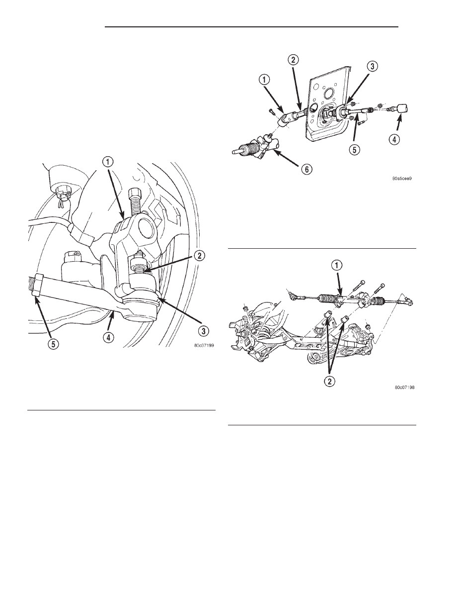
Fig. 4 Gear Coupler
1 – COUPLER
2 – LOWER SHAFT
3 – TOE PLATE
4 – STEERING COLUMN
5 – UPPER SHAFT
6 – RACK AND PINION STEERING GEAR
Fig. 5 Rack & Pinion Steering Gear - 4x2
1 – RACK AND PINION STEERING GEAR
2 – BUSHING
19 - 12
STEERING
DN
REMOVAL AND INSTALLATION (Continued)