Dodge Dakota (R1). Manual - part 561


  Index      Dodge     Dodge Dakota (R1) - service repair manual 2000 year


Search            


Content   ..  559  560  561  562   ..


Dodge Dakota (R1). Manual - part 561


(11) Gently rock and pull left fuel rail until fuel

injectors just start to clear intake manifold. Gently
rock and pull right fuel rail until fuel injectors just
start to clear intake manifold. Repeat this procedure
(left/right) until all fuel injectors have cleared intake
manifold.

(12) Remove fuel rail (with injectors attached)

from engine.

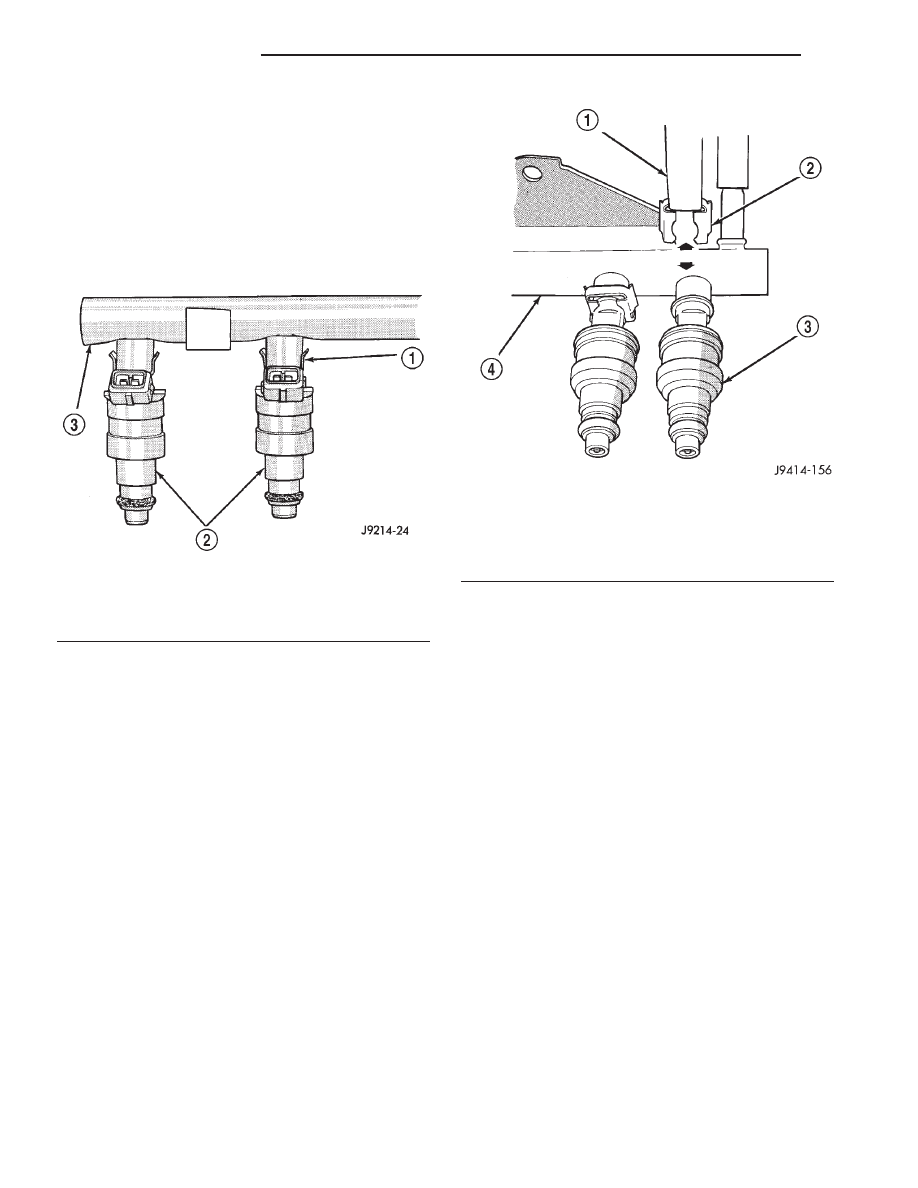
(13) Remove clip(s) retaining injector(s) to fuel rail

(Fig. 24) or (Fig. 25).

REMOVAL - 4.7L

WARNING: THE FUEL SYSTEM IS UNDER CON-
STANT

PRESSURE

EVEN

WITH

ENGINE

OFF.

BEFORE SERVICING FUEL RAIL, FUEL SYSTEM
PRESSURE MUST BE RELEASED.

CAUTION: The left and right fuel rails are replaced
as an assembly. Do not attempt to separate rail
halves at connector tube (Fig. 26). Due to design of
tube, it does not use any clamps. Never attempt to
install a clamping device of any kind to tube. When
removing fuel rail assembly for any reason, be care-
ful not to bend or kink tube.

(1) Remove fuel tank filler tube cap.
(2) Perform Fuel System Pressure Release Proce-

dure.

(3) Remove negative battery cable at battery.
(4) Remove air duct at throttle body air box.
(5) Remove air box at throttle body.
(6) Remove wiring at rear of generator.
(7) Disconnect fuel line latch clip and fuel line at

fuel rail. A special tool will be necessary for fuel line
disconnection. Refer to Quick-Connect Fittings.

(8) Remove vacuum lines at throttle body.
(9) Disconnect electrical connectors at all 8 fuel

injectors. To remove connector refer to (Fig. 27). Push
red colored slider away from injector (1). While push-
ing slider, depress tab (2) and remove connector (3)
from injector. The factory fuel injection wiring har-
ness is numerically tagged (INJ 1, INJ 2, etc.) for
injector position identification. If harness is not
tagged, note wiring location before removal.

(10) Disconnect electrical connectors at throttle

body.

(11) Disconnect electrical connectors at MAP and

IAT sensors.

(12) Remove first three ignition coils on each bank

(cylinders #1, 3, 5, 2, 4 and 6). Refer to Ignition Coil
Removal/Installation.

(13) Remove 4 fuel rail mounting bolts (Fig. 26).
(14) Gently rock and pull left side of fuel rail until

fuel injectors just start to clear machined holes in
cylinder head. Gently rock and pull right side of rail
until injectors just start to clear cylinder head holes.
Repeat this procedure (left/right) until all injectors
have cleared cylinder head holes.

(15) Remove fuel rail (with injectors attached)

from engine.

(16) If fuel injectors are to be removed, refer to

Fuel Injector Removal/Installation.

Fig. 24 Fuel Injector

1 - CLIP
2 - INJECTOR
3 - FUEL RAIL

Fig. 25 Injector Retaining

1 - PLIERS
2 - INJECTOR CLIP
3 - FUEL INJECTOR
4 - FUEL RAIL

14 - 16

FUEL DELIVERY

AN

FUEL RAIL (Continued)

INSTALLATION - 2.5L

(1) Clean each injector bore at intake manifold.
(2) Apply a small amount of clean engine oil to

each injector o-ring. This will aid in installation.

(3) Position tips of all fuel injectors into the corre-

sponding injector bore in intake manifold. Seat injec-
tors into manifold.

(4) Install and tighten fuel rail mounting bolts to

11 ±3 N·m (100 ±25 in. lbs.) torque.

(5) Position crankshaft position sensor pigtail wire

harness clamp and wire harness to fuel rail mount-
ing stud. Install nut securing harness to fuel rail
mounting stud.

(6) Connect tagged injector harness connectors to

appropriate injector.

(7) Connect fuel line and fuel line latch clip to fuel

rail. Refer Quick-Connect Fittings in this group for
procedures.

(8) Install protective cap to pressure test port fit-

ting (if equipped).

(9) Install cable routing bracket to intake mani-

fold.

(10) Connect throttle cable at throttle body.
(11) Connect speed control cable at throttle body (if

equipped).

(12) Connect

automatic

transmission

cable

at

throttle body (if equipped).

(13) Install air tube (or duct) at top of throttle

body.

(14) Install fuel tank cap.
(15) Connect negative battery cable to battery.
(16) Start engine and check for fuel leaks.

INSTALLATION - 3.9L/5.2L/5.9L

WARNING: THE FUEL SYSTEM IS UNDER A CON-
STANT PRESSURE (EVEN WITH ENGINE TURNED
OFF). BEFORE SERVICING FUEL RAIL ASSEMBLY,
FUEL SYSTEM PRESSURE MUST BE RELEASED.

To release fuel pressure, refer to Fuel System Pres-

sure Release Procedure in this group.

Fig. 26 Fuel Rail Mounting—4.7L V-8 Engine

1 - MOUNTING BOLTS (4)
2 - INJ.#7
3 - INJ.#5
4 - QUICK-CONNECT FITTING
5 - INJ.#3
6 - FUEL INJECTOR RAIL
7 - INJ.#1
8 - CONNECTOR TUBE
9 - INJ.#2
10 - INJ.#4
11 - INJ.#6
12 - INJ.#8
13 - PRESSURE TEST PORT CAP

Fig. 27 Remove/Install Injector Connector—4.7L V-8

Engine

AN

FUEL DELIVERY

14 - 17

FUEL RAIL (Continued)

CAUTION: The left and right fuel rails are replaced
as an assembly. Do not attempt to separate rail
halves at connecting hose (Fig. 21). Due to the
design of this connecting hose, it does not use any
clamps. Never attempt to install a clamping device
of any kind to hose. When removing fuel rail
assembly for any reason, be careful not to bend or
kink connecting hose.

(1) Apply a small amount of clean engine oil to

each fuel injector o-ring. This will help in fuel rail
installation.

(2) Install injector(s) and injector clip(s) to fuel rail.
(3) Position fuel rail/fuel injector assembly to injec-

tor openings on intake manifold.

(4) Guide each injector into intake manifold. Be

careful not to tear injector o-ring.

(5) Push right fuel rail down until fuel injectors

have bottomed on injector shoulder. Push left fuel
rail down until fuel injectors have bottomed on injec-
tor shoulder.

(6) Install fuel rail mounting bolts.
(7) Connect electrical connector to intake manifold

air temperature sensor.

(8) Connect electrical connectors at all fuel injec-

tors. To install connector, refer to (Fig. 23). Push con-
nector onto injector (1) and then push and lock red
colored slider (2). Verify connector is locked to injec-
tor by lightly tugging on connector.

(9) Install A/C support bracket (if equipped).
(10) Install throttle body to intake manifold. Refer

to Throttle Body installation in this group.

(11) Install fuel tube (line) at side of fuel rail.

Refer to Quick-Connect Fittings for procedures.

(12) Install air cleaner.
(13) Connect battery cable to battery.
(14) Start engine and check for leaks.

INSTALLATION - 4.7L

(1) If fuel injectors are to be installed, refer to Fuel

Injector Removal/Installation.

(2) Apply a small amount of engine oil to each fuel

injector o-ring. This will help in fuel rail installation.

(3) Position fuel rail/fuel injector assembly to

machined injector openings in cylinder head.

(4) Guide each injector into cylinder head. Be care-

ful not to tear injector o-rings.

(5) Push right side of fuel rail down until fuel

injectors have bottomed on cylinder head shoulder.
Push left fuel rail down until injectors have bot-
tomed on cylinder head shoulder.

(6) Install 4 fuel rail mounting bolts and tighten to

27 N·m (20 ft. lbs.).

(7) Install ignition coils. Refer to Ignition Coil

Removal/Installation.

(8) Connect electrical connectors to throttle body.

(9) Connect electrical connectors to MAP and IAT

sensors.

(10) Connect electrical connectors at all fuel injec-

tors. To install connector, refer to (Fig. 27). Push con-
nector onto injector (1) and then push and lock red
colored slider (2). Verify connector is locked to injec-
tor by lightly tugging on connector.

(11) Connect vacuum lines to throttle body.
(12) Connect fuel line latch clip and fuel line to

fuel rail. Refer to Quick-Connect Fittings.

(13) Connect wiring to rear of generator.
(14) Install air box to throttle body.
(15) Install air duct to air box.
(16) Connect battery cable to battery.
(17) Start engine and check for leaks.

FUEL TANK

DESCRIPTION

The fuel tank is constructed of a plastic material.

Its main functions are for fuel storage and for place-
ment of the fuel pump module.

OPERATION

All models pass a full 360 degree rollover test without

fuel leakage. To accomplish this, fuel and vapor flow
controls are required for all fuel tank connections.

A rollover valve(s) is mounted into the top of the

fuel tank (or pump module). Refer to Rollover Valve
information.

An evaporation control system is connected to the

rollover valve(s) to reduce emissions of fuel vapors
into the atmosphere. When fuel evaporates from the
fuel tank, vapors pass through vent hoses or tubes to
a charcoal canister where they are temporarily held.
When the engine is running, the vapors are drawn
into the intake manifold. Certain models are also
equipped with a self-diagnosing system using a Leak
Detection Pump (LDP). Refer to Emission Control
System for additional information.

REMOVAL

WARNING: THE FUEL SYSTEM IS UNDER A CON-
STANT PRESSURE (EVEN WITH ENGINE OFF).
BEFORE DRAINING FUEL TANK, FUEL SYSTEM
PRESSURE MUST BE RELEASED.

The fuel tank cannot be drained through the fill

or vent fittings at the top of the fuel tank. Two dif-
ferent procedures may be used to drain fuel tank
(using an approved gasoline draining station, or
using the DRB scan tool along with an approved gas-
oline draining station). Draining is done from the dis-
connected fuel line, at the fuel rail, with either
procedure.

14 - 18

FUEL DELIVERY

AN

FUEL RAIL (Continued)

(1) Remove fuel tank filler tube cap.
(2) Perform Fuel System Pressure Release proce-

dure.

(3) Disconnect negative battery cable at battery.
(4) Disconnect quick-connect fuel line at fuel rail.

Refer to Quick-Connect Fittings for procedures.

(5) The hose from the gasoline draining station

must be adapted into the 5/16” quick-connect fitting
on disconnected fuel line. One way to accomplish this
is to obtain a 5/16” test fitting such as from Snap-On
t Fuel Injection Adapter Set # FIDA44. Snap the fit-
ting into the disconnected fuel line and attach hose
from gasoline draining station.

(6) Operate the gasoline draining station to drain

fuel tank. As an alternative procedure, the electric
fuel pump may be activated. Refer to DRB scan tool
for fuel pump activation procedures. Activate electric
fuel pump, or gasoline draining station, and drain
tank until empty. If electric fuel pump is not operat-
ing, the gasoline draining station must be used.

(7) Raise vehicle and remove splash shield in front

of left/rear wheelhouse.

(8) Remove hose clamps and disconnect rubber fill

and vent hoses (Fig. 29) at fill and vent tubes (Fig.
28). Do not disconnect hoses at fuel tank.

Fig. 28 Fuel Fill and Vent Tubes

1 - FUEL FILL TUBE
2 - L.R. BRAKE DRUM
3 - FUEL VENT TUBE

Fig. 29 Fuel Tank and Hoses

1 - FUEL TANK (4—DOOR)
2 - TANK FITTINGS
3 - FILL HOSE
4 - VENT HOSE
5 - FUEL TUBE ASSEMBLY
6 - VENT HOSE

7 - TANK FITTINGS
8 - FUEL TANK (4—DOOR)
9 - FILL HOSE
10 - CLAMPS

AN

FUEL DELIVERY

14 - 19

FUEL TANK (Continued)


Content   ..  559  560  561  562   ..