Dodge Dakota (R1). Manual - part 474
INSPECTION
Inspect all surfaces with a straightedge if there is
any reason to suspect leakage. If out-of-flatness
exceeds
0.00075mm/mm
(0.0001in./in.)
times
the
span length in any direction, either replace head or
lightly machine the head surface.
FOR EXAMPLE:—A 305 mm (12 in.) span is
0.102 mm (0.004 in.) out-of-flat. The allowable out-of-
flat is 305 x 0.00075 (12 x 0.00075) equals 0.23 mm
(0.009 in.). This amount of out-of-flat is acceptable.
The
cylinder
head
surface
finish
should
be
1.78-3.00 microns (70-125 microinches).
Inspect push rods. Replace worn or bent rods.
INSTALLATION
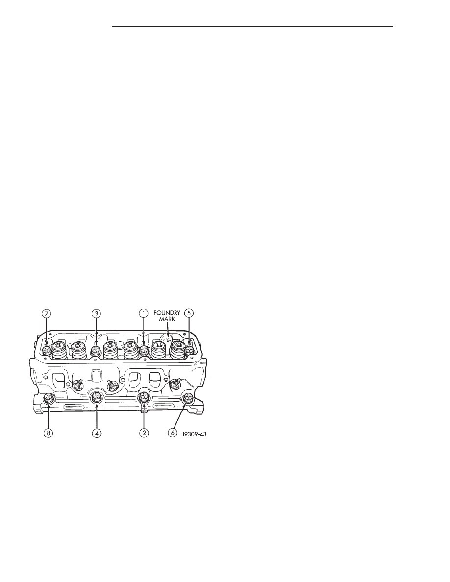
The alloy cast iron cylinder heads (Fig. 8) are held
in place by eight bolts. The spark plugs are located
at the peak of the wedge between the valves.
(1) Position the new cylinder head gaskets onto
the cylinder block.
(2) Position the cylinder heads onto head gaskets
and cylinder block.
(3) Starting at top center, tighten all cylinder head
bolts, in sequence, to 68 N·m (50 ft. lbs.) torque (Fig.
8). Repeat procedure, tighten all cylinder head bolts
to 143 N·m (105 ft. lbs.) torque. Repeat procedure to
confirm that all bolts are at 143 N·m (105 ft. lbs.)
torque.
CAUTION: When tightening the rocker arm bolts, be
sure the piston in that cylinder is NOT at TDC. Con-
tact between the valves and piston could occur.
(4) Install push rods and rocker arm assemblies in
their original positions. Tighten the bolts to 28 N·m
(21 ft. lbs.) torque.
(5) Install the intake manifold (Refer to 9 -
ENGINE/MANIFOLDS/INTAKE
MANIFOLD
-
INSTALLATION) and throttle body assembly.
(6) Install
exhaust
manifolds
(Refer
to
9
-
ENGINE/MANIFOLDS/EXHAUST
MANIFOLD
-
INSTALLATION).
(7) Adjust spark plugs to specifications. Install the
plugs and tighten to 41 N·m (30 ft. lbs.) torque.
(8) Install coil wires.
(9) Connect coolant temperature sending unit wire.
(10) Connect the fuel injector harness.
(11) Connect the vacuum supply hoses to the
intake manifold.
(12) Connect the heater hoses and bypass hose.
(13) Install distributor cap and wires.
(14) Connect the accelerator linkage and, if so
equipped, the speed control and transmission kick-
down cables.
(15) Install the fuel supply line.
(16) Install the generator and accessory drive belt
(Refer to 7 - COOLING/ACCESSORY DRIVE/DRIVE
BELTS
-
INSTALLATION).
Tighten
generator
mounting bolt to 41 N·m (30 ft. lbs.) torque.
(17) Install
the
intake
manifold-to-generator
bracket support rod. Tighten the bolts.
(18) Install cylinder head covers. (Refer to 9 -
ENGINE/CYLINDER
HEAD/CYLINDER
HEAD
COVER(S) - INSTALLATION).
(19) Install closed crankcase ventilation system.
(20) Connect the evaporation control system.
(21) Install the resonator assembly, air in-let hose
and air cleaner.
(22) Install the heat shields. Tighten the bolts to
41 N·m (30 ft. lbs.) torque.
(23) Fill cooling system (Refer to 7 - COOLING -
STANDARD PROCEDURE).
(24) Connect the battery negative cable.
CYLINDER HEAD COVER(S)
DESCRIPTION—CYLINDER HEAD COVER
GASKET
The cylinder head cover gasket (Fig. 9) is a steel-
backed silicone gasket, designed for long life usage.
REMOVAL
A steel-backed silicone gasket is used with the cyl-
inder head cover (Fig. 10). This gasket can be used
again.
(1) Disconnect the negative cable from the battery.
(2) Disconnect closed ventilation system and evap-
oration control system from cylinder head cover.
(3) Remove cylinder head cover bolts, cover and
gasket. The gasket may be used again.
CLEANING
Clean cylinder head cover gasket surface.
Clean head rail, if necessary.
Fig. 8 Cylinder Head Bolt -Tightening Sequence
9 - 84
ENGINE 3.9L
AN
CYLINDER HEAD (Continued)