Dodge Dakota (R1). Manual - part 321
(Connector C2) for the instrument cluster. Check for
continuity to a good ground. There should be no con-
tinuity. If OK, go to Step 4. If not OK, repair the
shorted fused panel lamps dimmer switch signal cir-
cuit between the instrument cluster and the JB as
required.
(4) Reinstall the instrument panel dimmer fuse
(Fuse 9 - 5 ampere) in the JB. Reconnect the battery
negative cable. Turn the exterior lamps On with the
headlamp switch. Rotate the headlamp switch panel
lamps dimmer thumbwheel upward to just before the
interior lamps detent. Check for battery voltage at
the fused panel lamps dimmer switch signal circuit
cavity of the instrument panel wire harness connec-
tor (Connector C2) for the instrument cluster. If OK,
replace the faulty bulb and bulb holder units. If not
OK, repair the open fused panel lamps dimmer
switch signal circuit between the instrument cluster
and the JB as required.
REMOVAL
WARNING: ON VEHICLES EQUIPPED WITH AIR-
BAGS, DISABLE THE AIRBAG SYSTEM BEFORE
ATTEMPTING ANY STEERING WHEEL, STEERING
COLUMN, OR INSTRUMENT PANEL COMPONENT
DIAGNOSIS OR SERVICE. DISCONNECT AND ISO-
LATE THE BATTERY NEGATIVE (GROUND) CABLE,
THEN WAIT TWO MINUTES FOR THE AIRBAG SYS-
TEM CAPACITOR TO DISCHARGE BEFORE PER-
FORMING FURTHER DIAGNOSIS OR SERVICE. THIS
IS THE ONLY SURE WAY TO DISABLE THE AIRBAG
SYSTEM. FAILURE TO TAKE THE PROPER PRE-
CAUTIONS COULD RESULT IN ACCIDENTAL AIR-
BAG DEPLOYMENT AND POSSIBLE PERSONAL
INJURY.
(1) Disconnect and isolate the battery negative
cable.
(2) Remove the cluster bezel from the instrument
panel. (Refer to 23 - BODY/INSTRUMENT PANEL/
CLUSTER BEZEL - REMOVAL).
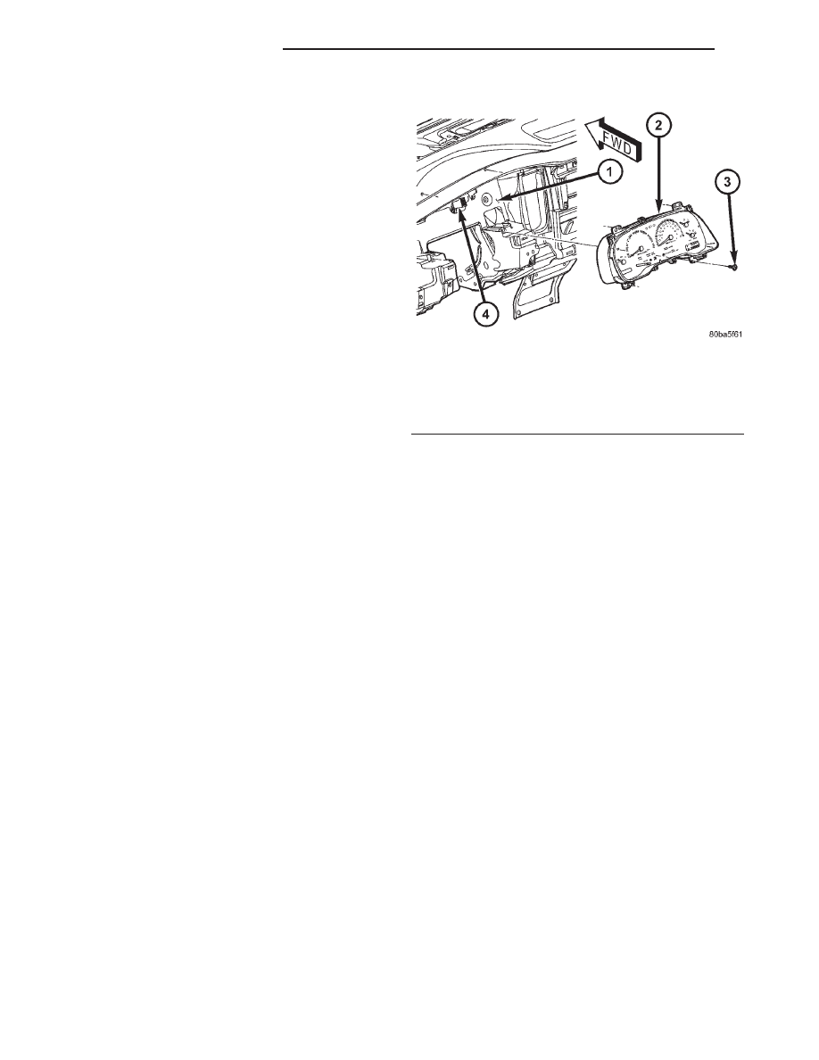
(3) Remove the four screws that secure the instru-
ment cluster to the instrument panel (Fig. 2).
(4) Pull
the
instrument
cluster
rearward
far
enough to disengage the two self-docking instrument
panel wire harness connectors from the cluster con-
nector receptacles.
(5) Roll the bottom of the instrument cluster
upward and rearward to remove it from the instru-
ment panel.
DISASSEMBLY
Some of the components for the instrument cluster
used in this vehicle are serviced individually. The
serviced
components
include:
the
incandescent
instrument cluster indicator lamp and illumination
lamp bulbs (including the integral bulb holders), the
cluster lens and hood unit, and the cluster housing
rear cover. The remaining components are serviced
only as a part of the cluster housing unit, which
includes: the cluster housing, the electronic circuit
board unit, the cluster overlay, the gauges, and the
odometer/trip odometer reset switch button. Follow-
ing are the procedures for disassembling the serviced
components from the instrument cluster unit.
WARNING: ON VEHICLES EQUIPPED WITH AIR-
BAGS, DISABLE THE AIRBAG SYSTEM BEFORE
ATTEMPTING ANY STEERING WHEEL, STEERING
COLUMN, OR INSTRUMENT PANEL COMPONENT
DIAGNOSIS OR SERVICE. DISCONNECT AND ISO-
LATE THE BATTERY NEGATIVE (GROUND) CABLE,
THEN WAIT TWO MINUTES FOR THE AIRBAG SYS-
TEM CAPACITOR TO DISCHARGE BEFORE PER-
FORMING FURTHER DIAGNOSIS OR SERVICE. THIS
IS THE ONLY SURE WAY TO DISABLE THE AIRBAG
SYSTEM. FAILURE TO TAKE THE PROPER PRE-
CAUTIONS COULD RESULT IN ACCIDENTAL AIR-
BAG DEPLOYMENT AND POSSIBLE PERSONAL
INJURY.
CLUSTER BULB
This procedure applies to each of the incandescent
cluster illumination lamp or indicator lamp bulb and
bulb holder units. However, the illumination lamps
and the indicator lamps use different bulb and bulb
holder unit sizes. They must never be interchanged.
(1) Disconnect and isolate the battery negative
cable.
Fig. 2 Instrument Cluster Remove/Install
1 - INSTRUMENT PANEL
2 - INSTRUMENT CLUSTER
3 - SCREW (4)
4 - SELF-DOCKING CONNECTOR (2)
8J - 10
INSTRUMENT CLUSTER
AN
INSTRUMENT CLUSTER (Continued)