Dodge Dakota (R1). Manual - part 319


  Index      Dodge     Dodge Dakota (R1) - service repair manual 2000 year


Search            


Content   ..  317  318  319  320   ..


Dodge Dakota (R1). Manual - part 319


WASHER FLUID INDICATOR

DESCRIPTION . . . . . . . . . . . . . . . . . . . . . . . . . . . 35
OPERATION. . . . . . . . . . . . . . . . . . . . . . . . . . . . . 35
DIAGNOSIS AND TESTING . . . . . . . . . . . . . . . . . 36

WASHER FLUID INDICATOR . . . . . . . . . . . . . . 36

WATER-IN-FUEL INDICATOR

DESCRIPTION . . . . . . . . . . . . . . . . . . . . . . . . . . . 37
OPERATION. . . . . . . . . . . . . . . . . . . . . . . . . . . . . 37

INSTRUMENT CLUSTER

DESCRIPTION

The instrument cluster for this model is an Elec-

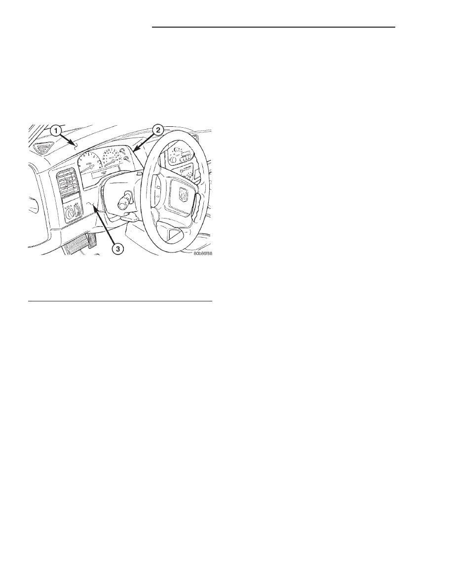
troMechanical Instrument Cluster (EMIC) module
that is located in the instrument panel above the
steering column opening, directly in front of the
driver (Fig. 1). The EMIC gauges and indicators are
protected by an integral clear plastic cluster lens,
and are visible through a dedicated opening in the
cluster bezel on the instrument panel. Just behind
the cluster lens is the cluster hood and integral clus-
ter mask, which are constructed of molded black
plastic. The cluster hood serves as a visor and shields
the face of the cluster from ambient light and reflec-
tions to reduce glare, while the cluster mask serves
to separate the define the individual gauges and the
information center area of the EMIC. Behind the
cluster hood and mask is the cluster overlay and
gauges. The overlay is a laminated plastic unit. The
dark, visible surface of the outer layer of the overlay
is marked with all of the gauge identification and
graduations, but this layer is also translucent. The
darkness of this outer layer prevents the cluster from
appearing cluttered or busy by concealing the cluster
indicators that are not illuminated, while the trans-
lucence of this layer allows those indicators and icons
that are illuminated to be readily visible. The under-
lying layer of the overlay is opaque and allows light

from the various indicators and illumination lamps
behind it to be visible through the outer layer of the
overlay only through predetermined cutouts. On the
lower edge of the cluster lens just left of center, the
odometer/trip

odometer

switch

knob

protrudes

through dedicated holes in the cluster mask and the
cluster lens. The remainder of the EMIC, including
the mounts and the electrical connections, are con-
cealed behind the cluster bezel. The molded plastic
EMIC housing has four integral mounting tabs, two
each on the upper and lower edges of the housing.
The EMIC is secured to the molded plastic instru-
ment panel cluster carrier with four screws. All elec-
trical connections to the EMIC are made at the back
of the cluster housing through two take outs of the
instrument panel wire harness, each equipped with a
self-docking connector.

A single EMIC module is offered on this model;

however, some variations of this module exist due to
optional equipment and regulatory requirements.
This module utilizes integrated circuitry and infor-
mation carried on the Programmable Communica-
tions Interface (PCI) data bus network for control of
all gauges and many of the indicators. (Refer to 8 -
ELECTRICAL/ELECTRONIC

CONTROL

MOD-

ULES/COMMUNICATION - DESCRIPTION). The
EMIC also uses several hard wired inputs in order to
perform its many functions. In addition to instru-
mentation and indicators, the EMIC has hardware
and/or software to support the following functions:

• Chime Warning Requests - The EMIC sends

chime tone requests over the PCI data bus network
to the Central Timer Module (CTM) when it monitors
certain conditions or inputs. The CTM replaces the
chime or buzzer module and performs the functions
necessary to provide audible alerts that are synchro-
nized with the visual alerts provided by the EMIC.
(Refer

to

8

-

ELECTRICAL/CHIME/BUZZER

-

DESCRIPTION).

• Vacuum Fluorescent Display (VFD) Dim-

ming Service - The EMIC performs the functions
necessary to eliminate the need for a separate VFD
dimming module by providing control and synchroni-
zation of the illumination intensity of all vacuum flu-
orescent displays in the vehicle, as well as a parade
mode.

The EMIC module incorporates a blue-green digital

VFD for displaying odometer and trip odometer infor-
mation, as well as the amber cruise indicator display
function. Some variations of the EMIC are necessary
to

support

optional

equipment

and

regulatory

requirements. The EMIC includes the following ana-
log gauges:

Fig. 1 Instrument Cluster

1 - INSTRUMENT PANEL TOP COVER
2 - INSTRUMENT CLUSTER
3 - CLUSTER BEZEL

8J - 2

INSTRUMENT CLUSTER

AN

• Coolant Temperature Gauge

• Fuel Gauge

• Oil Pressure Gauge

• Speedometer

• Tachometer

• Voltage Gauge
The EMIC also includes provisions for the follow-

ing indicators:

• Airbag Indicator

• Antilock Brake System (ABS) Indicator

• Brake Indicator

• Check Gauges Indicator

• Coolant Low Indicator (Diesel Engine Only)

• Cruise Indicator (Odometer VFD)

• Door Ajar Indicator

• High Beam Indicator

• Low Fuel Indicator

• Malfunction Indicator Lamp (MIL)

• Overdrive-Off Indicator (Automatic Trans-

mission Only)

• Seatbelt Indicator

• Security Indicator

• Service Four-Wheel Drive Indicator

• Transmission Overtemp Indicator

• Turn Signal (Right and Left) Indicators

• Upshift Indicator

• Wait-To-Start

Indicator

(Diesel

Engine

Only)

• Washer Fluid Indicator

• Water-In-Fuel Indicator (Diesel Engine

Only)

Some of these indicators are either programmable

or automatically configured when the EMIC is con-
nected to the vehicle electrical system. This feature
allows those indicators to be activated or deactivated
for compatibility with certain optional equipment. On
models equipped with an automatic transmission, the
EMIC also incorporates a blue-green digital VFD in
the lower right corner of the cluster for displaying
the transmission gear that has been selected with
the automatic transmission gear selector lever, as
well as the amber overdrive-off indicator display
function.

Cluster illumination is accomplished by adjustable

incandescent back lighting, which illuminates the
gauges for visibility when the exterior lighting is
turned on. The EMIC high beam indicator, turn sig-
nal indicators, and wait-to-start indicator are also
illuminated by dedicated incandescent bulbs. The
remaining indicators in the EMIC are each illumi-
nated by a dedicated Light Emitting Diode (LED)
that is soldered onto the electronic circuit board.
Each of the incandescent bulbs is secured by an inte-
gral bulb holder to the electronic circuit board from
the back of the cluster housing.

Hard wired circuitry connects the EMIC to the

electrical system of the vehicle. These hard wired cir-
cuits are integral to several wire harnesses, which
are routed throughout the vehicle and retained by
many different methods. These circuits may be con-
nected to each other, to the vehicle electrical system
and to the EMIC through the use of a combination of
soldered splices, splice block connectors, and many
different types of wire harness terminal connectors
and insulators. Refer to the appropriate wiring infor-
mation. The wiring information includes wiring dia-
grams, proper wire and connector repair procedures,
further details on wire harness routing and reten-
tion, as well as pin-out and location views for the
various wire harness connectors, splices and grounds.

The EMIC modules for this model are serviced only

as complete units. The EMIC module cannot be
adjusted or repaired. If a gauge, an LED indicator,
the VFD, the electronic circuit board, the circuit
board hardware, the cluster overlay, or the EMIC
housing are damaged or faulty, the entire EMIC mod-
ule must be replaced. The cluster lens and the hood
and mask unit, the rear cluster housing cover, and
the incandescent lamp bulbs with holders are avail-
able for individual service replacement.

OPERATION

The ElectroMechanical Instrument Cluster (EMIC)

is designed to allow the vehicle operator to monitor
the conditions of many of the vehicle components and
operating systems. The gauges and indicators in the
EMIC provide valuable information about the various
standard and optional powertrains, fuel and emis-
sions systems, cooling systems, lighting systems,
safety systems and many other convenience items.
The EMIC is installed in the instrument panel so
that all of these monitors can be easily viewed by the
vehicle operator when driving, while still allowing
relative ease of access for service. The microproces-
sor-based EMIC hardware and software uses various
inputs to control the gauges and indicators visible on
the face of the cluster. Some of these inputs are hard
wired, but most are in the form of electronic mes-
sages that are transmitted by other electronic mod-
ules

over

the

Programmable

Communications

Interface (PCI) data bus network. (Refer to 8 -
ELECTRICAL/ELECTRONIC

CONTROL

MOD-

ULES/COMMUNICATION - OPERATION).

The EMIC microprocessor smooths the input data

using algorithms to provide gauge readings that are
accurate, stable and responsive to operating condi-
tions. These algorithms are designed to provide
gauge readings during normal operation that are con-
sistent with customer expectations. However, when
abnormal conditions exist, such as low/high battery
voltage, low oil pressure, or high coolant tempera-

AN

INSTRUMENT CLUSTER

8J - 3

INSTRUMENT CLUSTER (Continued)

ture, the algorithm drives the gauge pointer to an
extreme position and the microprocessor turns on a
“Check Gauges” indicator to provide a distinct visual
indication of a problem to the vehicle operator. The
instrument cluster circuitry may also generate an
electronic chime tone request message to the Central
Timer Module (CTM) over the PCI data bus when it
monitors certain conditions or inputs, in order to pro-
vide the vehicle operator with an audible alert to
supplement a visual indication. One such alert is a
turn signal warning chime, which the EMIC provides
by monitoring the turn signal indicators and PCI bus
messages from the PCM for vehicle speed and dis-
tance. If the EMIC determines that a turn signal is
left on for a distance greater than about 1.6 kilome-
ters (1 mile) at a vehicle speed greater than about 24
kilometers per hour (15 miles per hour), it will send
an electronic message to the CTM requesting a con-
tinuous chime to sound until the turn signal is
turned off or the vehicle speed is less than 24 kilo-
meters per hour (15 miles per hour).

The EMIC circuitry operates on battery current

received through a fused B(+) fuse in the Junction
Block (JB) on a non-switched fused B(+) circuit, and
on battery current received through a fused ignition
switch output (run-start) fuse in the JB on a fused
ignition

switch

output

(run-start)

circuit.

This

arrangement allows the EMIC to provide some fea-
tures regardless of the ignition switch position, while
other features will operate only with the ignition
switch in the On or Start positions. The EMIC cir-
cuitry is grounded through two separate ground cir-
cuits located in one of the two instrument cluster
connectors and take outs of the instrument panel
wire harness. One ground circuit receives ground
through a take out with an eyelet terminal connector
of the instrument panel wire harness that is secured
by a nut to a ground stud located on the left cowl
side inner panel below the instrument panel, while
the other ground circuit receives ground through a
take out with an eyelet terminal connector of the
headlamp and dash wire harness that is secured by a
nut to a ground stud located on the left front fender
inner shield near the battery in the engine compart-
ment.

The EMIC also has a self-diagnostic actuator test

capability, which will test each of the PCI bus mes-
sage-controlled functions of the cluster by lighting
the appropriate indicators and positioning the gauge
needles at several predetermined locations on the
gauge faces in a prescribed sequence. (Refer to 8 -
ELECTRICAL/INSTRUMENT CLUSTER - DIAGNO-
SIS AND TESTING). See the owner’s manual in the
vehicle glove box for more information on the fea-
tures, use and operation of the EMIC.

GAUGES

All gauges receive battery current through the

EMIC circuitry when the ignition switch is in the On
or Start positions. With the ignition switch in the Off
position battery current is not supplied to any
gauges, and the EMIC circuitry is programmed to
move all of the gauge needles back to the low end of
their respective scales. Therefore, the gauges do not
accurately indicate any vehicle condition unless the
ignition switch is in the On or Start positions. All of
the EMIC gauges, except the odometer, are air core
magnetic units. Two fixed electromagnetic coils are
located within each gauge. These coils are wrapped
at right angles to each other around a movable per-
manent magnet. The movable magnet is suspended
within the coils on one end of a pivot shaft, while the
gauge needle is attached to the other end of the
shaft. One of the coils has a fixed current flowing
through it to maintain a constant magnetic field
strength. Current flow through the second coil
changes, which causes changes in its magnetic field
strength. The current flowing through the second coil
is changed by the EMIC circuitry in response to mes-
sages received over the PCI data bus. The gauge nee-
dle moves as the movable permanent magnet aligns
itself to the changing magnetic fields created around
it by the electromagnets.

The gauges are diagnosed using the EMIC self-di-

agnostic actuator test. (Refer to 8 - ELECTRICAL/
INSTRUMENT

CLUSTER

-

DIAGNOSIS

AND

TESTING). Proper testing of the PCI data bus and
the data bus message inputs to the EMIC that con-
trol each gauge require the use of a DRBIII

t scan

tool. Refer to the appropriate diagnostic information.
Specific operation details for each gauge may be
found elsewhere in this service manual.

VACUUM-FLUORESCENT DISPLAY

The Vacuum-Fluorescent Display (VFD) module is

soldered to the EMIC circuit board. The display is
active with the ignition switch in the On or Start
positions, and inactive when the ignition switch is in
any other position. The VFD has several display
capabilities including odometer, trip odometer, and
an

amber

“CRUISE”

indication

whenever

the

optional speed control system is turned On. The
cruise indicator function of the VFD is automatically
enabled or disabled by the EMIC circuitry based
upon whether the vehicle is equipped with the speed
control option. An odometer/trip odometer switch on
the EMIC circuit board is used to control several of
the display modes. This switch is actuated manually
by depressing the odometer/trip odometer switch but-
ton that extends through the lower edge of the clus-
ter lens, just left of center. Actuating this switch
momentarily with the ignition switch in the On posi-

8J - 4

INSTRUMENT CLUSTER

AN

INSTRUMENT CLUSTER (Continued)

tion will toggle the VFD between the odometer and
trip odometer modes. The word “TRIP” will also
appear in blue-green text when the VFD trip odome-
ter mode is active. Depressing the switch button for
about two seconds while the VFD is in the trip odom-
eter mode will reset the trip odometer value to zero.
Holding this switch depressed while turning the igni-
tion switch from the Off position to the On position
will activate the EMIC self-diagnostic actuator test.
The EMIC will automatically flash the odometer or
trip odometer information on and off if there is a loss
of PCI data bus communication. The VFD will also
display various information used in several diagnos-
tic procedures. Refer to the appropriate diagnostic
information for additional details on this VFD func-
tion.

Models equipped with an automatic transmission

have a second VFD soldered to the EMIC circuit
board, which serves as the electronic transmission
gear selector indicator. Like the odometer/trip odom-
eter VFD, this display is active with the ignition
switch in the On or Start positions, and inactive
when the ignition switch is in any other position.
This VFD also has an amber “O/D OFF” indicator
that illuminates when the automatic transmission
electronic overdrive is turned off by depressing the
overdrive-off switch button located in the knob on the
end of the gear selector lever on the right side of the
steering column. This VFD displays the characters
“P,” “R,” “N,” “D,” “2,”and “1,” which represent each of
the available gear selector positions. A small rectan-
gular box is illuminated around the character repre-
senting the gear position that is currently selected.

Both VFDs are diagnosed using the EMIC self-di-

agnostic actuator test. (Refer to 8 - ELECTRICAL/
INSTRUMENT

CLUSTER

-

DIAGNOSIS

AND

TESTING). Proper testing of the PCI data bus and
the data bus message inputs to the EMIC that con-
trol some of the VFD functions requires the use of a
DRBIII

t scan tool. Refer to the appropriate diagnos-

tic information. Specific operation details for the
odometer, trip odometer, gear selector indicator,
cruise indicator, and overdrive-off indicator functions
of these VFDs may be found elsewhere in this service
manual.

INDICATORS

Indicators are located in various positions within

the EMIC and are all connected to the EMIC circuit
board. The high beam indicator, washer fluid indica-
tor, turn signal indicators, and the diesel engine
wait-to-start indicator are hard wired. The brake
indicator is controlled by PCI data bus messages
from the Controller Anti-lock Brake (CAB) and the
hard wired park brake switch input to the EMIC.
The seatbelt indicator is controlled by the EMIC pro-

gramming, PCI data bus messages from the Airbag
Control Module (ACM), and the hard wired seat belt
switch input to the EMIC. The security indicator is
controlled by a hard wired Central Timer Module
(CTM) input to the EMIC, and by PCI data bus mes-
sages from the Sentry Key Immobilizer Module
(SKIM) if the vehicle is equipped with the optional
Sentry Key Immobilizer System (SKIS). The Mal-
function Indicator Lamp (MIL) is normally controlled
by PCI data bus messages from the Powertrain Con-
trol Module (PCM); however, if the EMIC loses PCI
data bus communications, the EMIC circuitry will
automatically turn the MIL on, and flash the odom-
eter VFD on and off repeatedly until PCI data bus
communication is restored. The EMIC uses PCI data
bus messages from the CTM, the PCM, the Transfer
Case Control Module (TCCM), the ACM, and the
CAB to control all of the remaining indicators. Differ-
ent indicators are controlled by different strategies;
some receive fused ignition switch output from the
EMIC circuitry cluster and have a switched ground,
while others are grounded through the EMIC cir-
cuitry and have a switched battery feed.

In addition, certain indicators in this instrument

cluster are programmable or configurable. This fea-
ture allows the programmable indicators to be acti-
vated or deactivated with a DRBIII

t scan tool, while

the configurable indicators will be automatically
enabled or disabled by the EMIC circuitry for com-
patibility with certain optional equipment. The only
programmable indicator for this model is the upshift
indicator. The cruise indicator, service 4WD indicator,
gear selector indicator, overdrive-off indicator, and
the transmission overtemp indicator are automati-
cally configured, either electronically or mechanically.
If the EMIC is disconnected from the fused B(+) cir-
cuit for more than about five minutes the EMIC will
forget its previous electronic configuration settings,
but will learn the proper indicator configuration set-
tings again when it is reinstalled in a vehicle.

The hard wired indicators are diagnosed using con-

ventional diagnostic methods. The EMIC and PCI
bus message controlled indicator lamps are diagnosed
using the EMIC self-diagnostic actuator test. (Refer
to 8 - ELECTRICAL/INSTRUMENT CLUSTER -
DIAGNOSIS AND TESTING). Proper testing of the
PCI data bus and the data bus message inputs to the
EMIC that control each indicator require the use of a
DRBIII

t scan tool. Refer to the appropriate diagnos-

tic information. Specific operation details for each
indicator may be found elsewhere in this service
manual.

CLUSTER ILLUMINATION

The EMIC has several illumination lamps that are

illuminated when the exterior lighting is turned on

AN

INSTRUMENT CLUSTER

8J - 5

INSTRUMENT CLUSTER (Continued)


Content   ..  317  318  319  320   ..