Dodge Dakota (R1). Manual - part 308
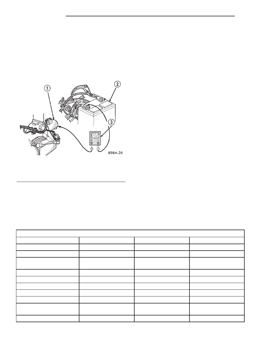
(5) Connect positive lead of voltmeter to starter
housing. Connect negative lead of voltmeter to bat-
tery negative terminal post (Fig. 6). Rotate and hold
ignition switch in Start position. Observe voltmeter.
If reading is above 0.2 volt, correct poor starter to
engine block ground contact. Note: If equipped
with a dual battery system (diesel), this proce-
dure must be performed on driver side battery
only.
(6) If equipped with dual battery system (diesel),
connect positive lead of voltmeter to driver side bat-
tery positive cable clamp. Connect negative lead of
voltmeter to passenger side battery positive terminal
post. Rotate and hold ignition switch in Start posi-
tion. Observe voltmeter. If reading is above 0.2 volt,
clean and tighten passenger side battery positive
cable eyelet connection at driver side battery positive
cable clamp bolt. Repeat test. If reading is still above
0.2 volt, replace faulty passenger side battery posi-
tive cable.
If resistance tests detect no feed circuit problems,
refer to Starter Motor in the Diagnosis and Testing.
CONTROL CIRCUIT TESTING
The starter control circuit components should be
tested in the order in which they are listed, as fol-
lows:
• Starter Relay - Refer to Starter Relay Diag-
nosis and Testing.
• Starter Solenoid - Refer to Starter Motor
Diagnosis and Testing.
• Ignition Switch - Refer to Ignition Switch
and Key Lock Cylinder
• Clutch Pedal Position Switch - If equipped
with manual transmission, refer to Clutch Pedal
Position Switch in 6, Clutch.
• Park/Neutral Position Switch - If equipped
with automatic transmission, refer to Park/Neutral
Position Switch in 21, Transmission.
• Wire harnesses and connections - Refer to 8,
Wiring Diagrams.
SPECIFICATIONS
SPECIFICATIONS - STARTING SYSTEM
Starter Motor and Solenoid
Manufacturer
Mitsubishi
Denso
Denso
Part Number
56041013AC
56027702AC
56028715
Engine Application
2.5L
3.9L, 4.7L (Manual), 5.9L
4.7L (Auto)
Power Rating
1.2 Kilowatt - (1.6
Horsepower)
1.4 Kilowatt - (1.9
Horsepower
1.4 Kilowatt - (1.9
Horsepower
Voltage
12 Volts
12 Volts
12 Volts
Pinion Teeth
9
10
10
Number of Fields
4
4
4
Number of Poles
4
4
4
Number of Brushes
4
4
4
Drive Type
Planetary Gear
Reduction
Reduction Gear Train
Reduction Gear Train
Free Running Test Voltage
11.2 Volts
11 Volts
11 Volts
Fig. 6 Test Starter Ground - Typical
1 - STARTER MOTOR
2 - BATTERY
3 - VOLTMETER
8Fa - 14
STARTING
R1
STARTING (Continued)