Dodge Dakota (R1). Manual - part 213
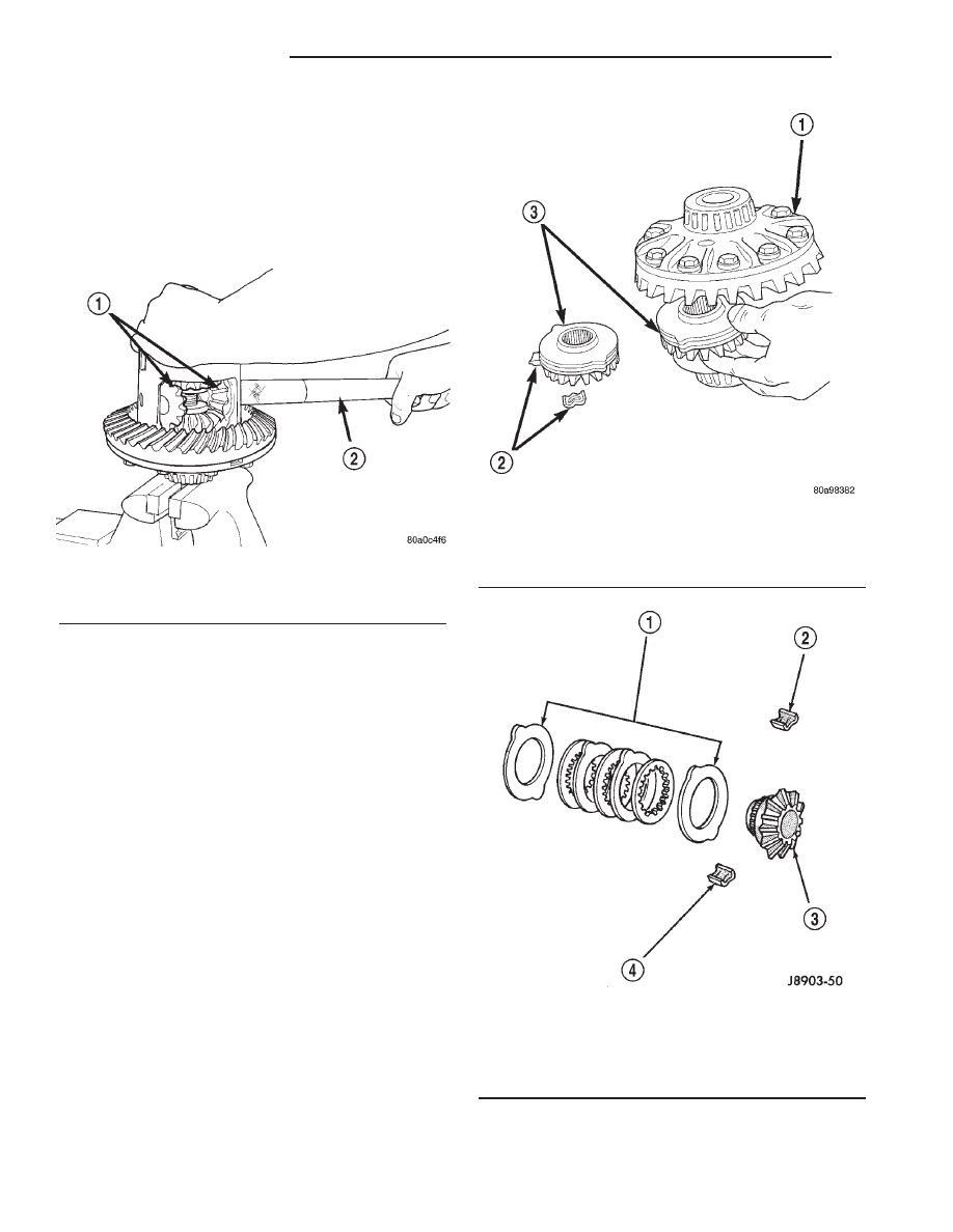
(10) Insert Turning Bar C-6960-2 into the pinion
mate shaft hole in the case (Fig. 39).
(11) Loosen the Forcing Screw in small increments
until the clutch pack tension is relieved and the dif-
ferential case can be turned using Turning Bar.
(12) Rotate differential case until the pinion gears
can be removed.
(13) Remove pinion gears from differential case.
(14) Remove
Forcing
Screw,
Step
Plate
and
Threaded Adapter.
(15) Remove top side gear, clutch pack retainer
and clutch pack. Keep plates in correct order during
removal (Fig. 40).
(16) Remove differential case from the Holding
Fixture. Remove side gear, clutch pack retainer and
clutch pack. Keep plates in correct order during
removal.
ASSEMBLY
Clean all components in cleaning solvent. Dry com-
ponents with compressed air. Inspect clutch pack
plates for wear, scoring or damage. Replace both
clutch packs if any one component in either pack is
damaged. Inspect side gears and pinions. Replace
any gear that is worn, cracked, chipped or damaged.
Inspect differential case and pinion shaft. Replace if
worn or damaged.
Lubricate each component with gear lubricant
before assembly.
(1) Assemble the clutch discs into packs and
secure disc packs with retaining clips (Fig. 41).
NOTE: New Plates and discs with fiber coating (no
grooves or lines) must be presoaked in Friction
Modifier before assembly. Soak plates and discs for
a minimum of 20 minutes.
Fig. 39 Pinion Gear
1 - PINION GEARS
2 - TURNING BAR
Fig. 40 Side Gear & Clutch Pack
1 - DIFFERENTIAL CASE
2 - RETAINER
3 - SIDE GEAR AND CLUTCH DISC PACK
Fig. 41 Clutch Disc Pack
1 - CLUTCH PACK
2 - RETAINER
3 - SIDE GEAR
4 - RETAINER
3 - 70
REAR AXLE - 8 1/4
AN
DIFFERENTIAL - TRAC-LOK (Continued)