Dodge Dakota (R1). Manual - part 97
•
Do not use the DRBIII
t if it has been damaged.
•
Do not use the test leads if the insulation is
damaged or if metal is exposed.
•
To avoid electrical shock, do not touch the test
leads, tips or the circuit being tested.
•
Choose the proper range and function for the
measurement. Do not try voltage or current mea-
surements that may exceed the rated capacity.
•
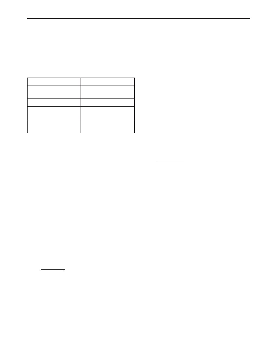
Do not exceed the limits shown in the table below:
FUNCTION
INPUT LIMIT
Volts
0 - 500 peak volts AC
0 - 500 volts DC
Ohms (resistance)*
0 - 1.12 megohms
Frequency Measured
Frequency Generated
0 - 10 kHz
Temperature
-58 - 1100°F
-50 - 600°C
* Ohms cannot be measured if voltage is present.
Ohms can be measured only in a non-powered
circuit.
•
Voltage between any terminal and ground must
not exceed 500v DC or 500v peak AC.
•
Use caution when measuring voltage above 25v
DC or 25v AC.
•
Use the low current shunt to measure circuits up
to 10A. Use the high current clamp to measure
circuits exceeding 10A.
•
When testing for the presence of voltage or cur-
rent, make sure the meter is functioning cor-
rectly. Take a reading of a known voltage or
current before accepting a zero reading.
•
When measuring current, connect the meter in
series with the load.
•
Disconnect the live test lead before disconnecting
the common test lead.
•
When using the meter function, keep the
DRBIII
t away from spark plug or coil wires to
avoid measuring error from outside interference.
4.3
WARNING
4.3.1
VEHICLE DAMAGE WARNINGS
Before disconnecting any control module, make
sure the ignition is ‘‘off ’’. Failure to do so could
damage the module.
When testing voltage or continuity at any control
module, use the terminal side (not the wire end) of
the connector. Do not probe a wire through the
insulation; this will damage it and eventually cause
it to fail because of corrosion.
Be careful when performing electrical tests so as
to prevent accidental shorting of terminals. Such
mistakes can damage fuses or components. Also, a
second code could be set, making diagnosis of the
original problem more difficult.
4.3.2
ROAD TESTING A COMPLAINT
VEHICLE
Some complaints will require a test drive as part
of the repair verification procedure. The purpose of
the test drive is to try to duplicate the diagnostic
code or symptom condition.
WARNING:
BEFORE
ROAD
TESTING
A
VEHICLE,
BE
SURE
THAT
ALL
COMPONENTS
ARE
REASSEMBLED.
DURING THE TEST DRIVE, DO NOT TRY TO
READ
THE
DRBIII
T
SCREEN
WHILE
IN
MOTION. DO NOT HANG THE DRBIII
T
FROM
THE REAR VIEW MIRROR OR OPERATE IT
YOURSELF.
HAVE
AN
ASSISTANT
AVAILABLE TO OPERATE THE DRBIII
T
.
4.4
DIAGNOSIS
1. Your diagnostic test procedure must begin
with a thorough visual inspection of the ABS sys-
tem components for damaged components or dis-
connected connectors.
A visual inspection consists of physically looking
for the possible cause of a malfunction. A careful
and thorough visual inspection of components may
quickly identify the cause of a malfunction and
eliminate the need for diagnostic testing.
PERFORM THE FOLLOWING VISUAL IN-
SPECTIONS BEFORE DOING ANY DIAGNOS-
TIC TESTING. If a malfunction is not resolved by
the visual inspection, proceed with diagnostic test-
ing according to the instructions in the manual.
See Section 8.0 (Component Locations) for pic-
tures identifying the location of system compo-
nents.
Brake Fluid
Level
Visually inspect for the proper
fluid level within the fluid reser-
voir.
Hydraulic
Control Unit
Visually inspect the hydraulic
assemblies for leaks and for
damaged or disconnected con-
nector.
Fuses
Visually inspect that all fuses
are properly installed.
7
GENERAL INFORMATION