Chrysler Le Baron, Dodge Dynasty, Plymouth Acclaim. Manual - part 577
BALANCE SHAFTS CARRIER ASSEMBLY
REMOVAL
The following components will remain intact dur-
ing carrier removal. Gear cover, gears, balance shafts
and the rear cover.
(1) Remove chain cover and driven balance shaft
chain sprocket screw.
(2) Loosen tensioner pivot and adjusting screws,
move driven balance shaft inboard through driven
chain sprocket. Sprocket will hang in lower chain
loop.
(3) Remove carrier to crankcase attaching bolts to
remove carrier.
INSTALLATION
Balance shaft and carrier assembly installation is
the reverse of the removal procedure. During instal-
lation crankshaft to balance shaft timing must be
established.
TIMING
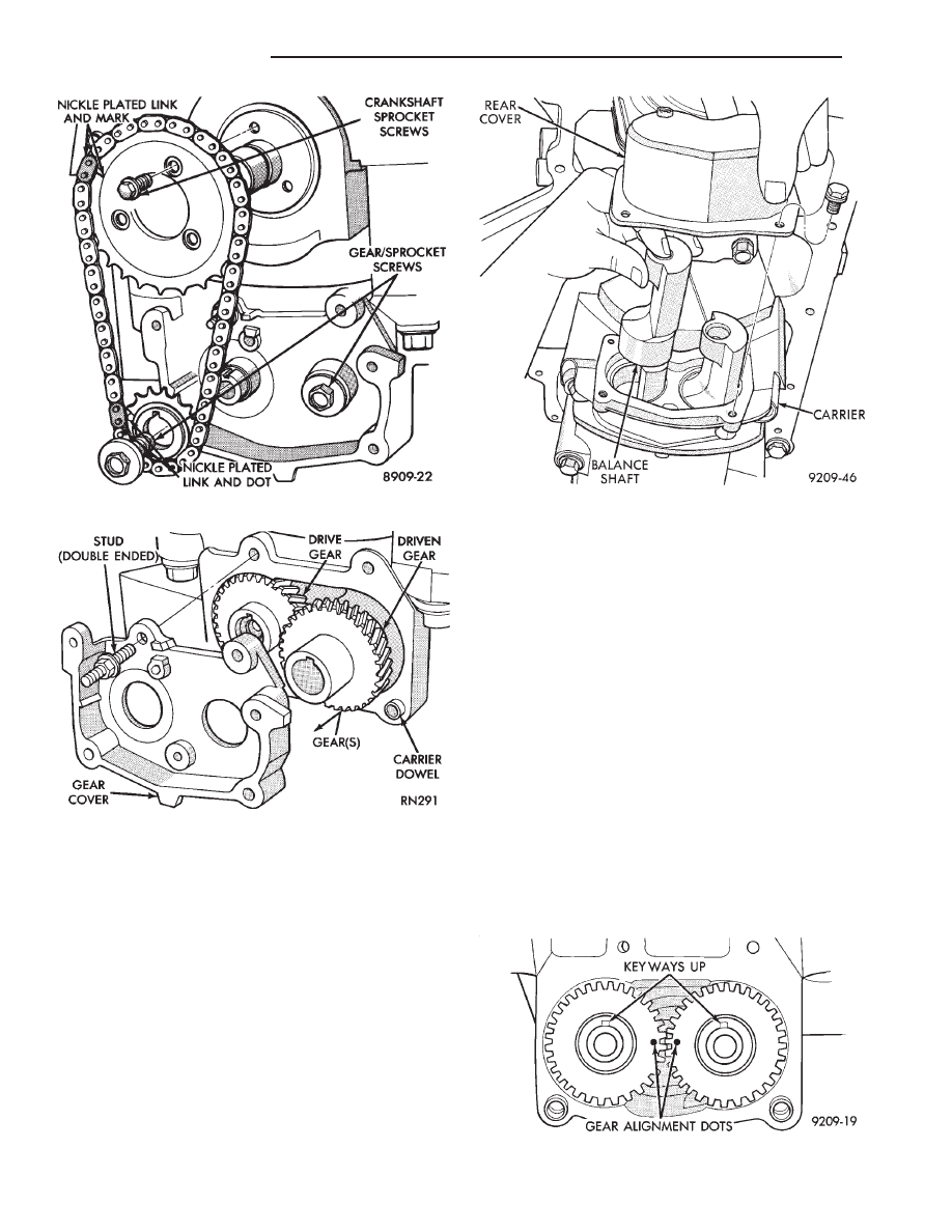
(1) With balance shafts installed in carrier (Fig. 19)
position carrier on crankcase and install six attaching
bolts and tighten to 54 N
Im (40 ft. lbs.).
(2) Turn balance shafts until both shaft key ways are
up Parallel to vertical centerline of engine. Install
short hub drive gear on sprocket driven shaft and long
hub gear on gear driven shaft. After installation gear
and balance shaft keyways must be up with gear
timing marks meshed as shown in (Fig. 20).
(3) Install gear cover and tighten double ended
stud/washer fastener to 12 N
Im (105 in. lbs.).
(4) Install crankshaft sprocket and tighten socket
head torx screws to 13 N
Im (130 in. lbs.).
Fig. 20 Gear Timing
Fig. 17 Drive Chain and Sprockets
Fig. 18 Gear Cover and Gears
Fig. 19 Balance Shaft(s) Remove/Install
9 - 46
2.2/2.5L ENGINE
Ä