Chrysler Le Baron, Dodge Dynasty, Plymouth Acclaim. Manual - part 575
INSTALLATION
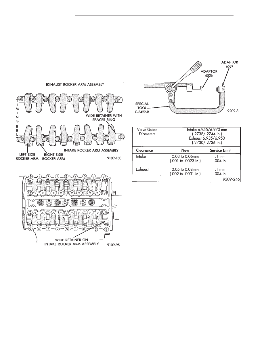
(1) Install rocker arm on the shaft in there origi-
nal position (Fig. 9).
(2) Install hydraulic lash adjusters making sure
that adjusters are at least partially full of oil. This is
indicated by little or no plunger travel when the lash
adjuster is depressed.
(3) Install rocker arm shaft assembly tighten in se-
quence shown in (Fig. 10).
(4) Install valve cover as previously outlined.
VALVE SPRINGS AND VALVE STEM SEALS
VALVE SERVICE
• CYLINDER HEAD MUST BE REMOVED TO
SERVICE VALVE SPRINGS AND VALVE STEM
SEALS.
VALVES AND VALVE SPRINGS
REMOVAL
(1) With cylinder head removed, compress valve
springs
using
Valve
Spring
Compressor
Tool
C-3422-B with adopters 6537 and 6526 (Fig. 11).
(2) Remove valve retaining locks, valve spring re-
tainers, valve stem seals and valve springs.
(3) Before removing valves, remove any burrs
from valve stem lock grooves to prevent damage
to the valve guides. Identify valves to insure instal-
lation in original location.
VALVE INSPECTION
(1) Clean valves thoroughly and discard burned,
warped and cracked valves.
(2) Measure valve stems for wear. Refer to (Fig. 14)
for specifications.
(3) Remove carbon and varnish deposits from inside
of valve guides with a reliable guide cleaner.
VALVE GUIDES
Measure valve guides in 3 places top, middle and
bottom (Fig. 13). Using a small hole gauge and a
micrometer, refer to (Fig. 12) for specifications.
Replace cylinder head if guides are not within
specifications.
TESTING VALVE SPRINGS
(1) Refer to Testing Valve previously described in
this Group for procedure. Test springs at 36.8 mm
(1-7/16 to 1-15/32 in.) 1000 N (225 lbs.)
6 40 N (9 lbs.).
Discard the springs that do not meet specifications.
(2) Inspect each valve spring for squareness with a
steel square and surface plate, test springs from both
ends. If the spring is more than 1.65mm (1/16 inch) out
of square, install a new spring. Spring free length is
53.2 mm
6.25 mm (2.094 in. 6.010 in.)
Fig. 9 Intake and Exhaust Rocker Arm Assemblies
Fig. 10 Rocker Arm Shaft—Installation
Fig. 11 Valve Spring Compressor
Fig. 12 Valve Guide Specification
9 - 38
2.2/2.5L ENGINE
Ä