Chrysler Le Baron, Dodge Dynasty, Plymouth Acclaim. Manual - part 363
(5) Reset the terminal locking tang, if it has one.
(6) Insert the removed wire in the same cavity on
the repair connector.
(7) Repeat steps four thru six for each wire in the
connector. Check that all wires are inserted into the
proper cavities. For connector pin out identification
refer to the wiring diagrams.
(8) Insert the connector locking wedge into the re-
paired connector.
(9) Connect connector to its mating half.
(10) Connect battery and test all affected systems.
CONNECTOR AND TERMINAL ASSEMBLY
REPLACEMENT
(1) Disconnect Battery.
(2) Disconnect the connector being repaired form
its mating half.
(3) Cut off the existing wire connector directly be-
hind the insulator. Remove six inches of tape from
the harness.
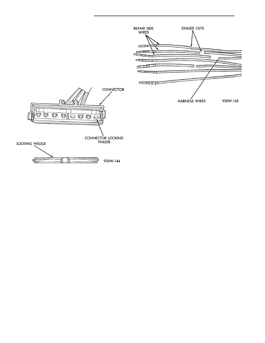
(4) Stagger cut all wires on the harness side about
1/2 inch apart (Fig. 14).
(5) Remove 1 inch of insulation from each wire on
the harness side.
(6) Stagger cut the matching wires on the repair
connector assembly in the opposite order as was done
on the harness side of the repair. Allow extra length
for soldered connections. Check that the overall
length is the same as the original (Fig. 14).
(7) Remove 1 inch of insulation from each wire.
(8) Place a piece of heat shrink tubing over one
side of the wire. Make sure the tubing will be long
enough to cover and seal the entire repair area.
(9) Spread the strands of the wire apart on each
part of the exposed wires (Fig. 11 example 1).
(10) Push the two ends of wire together until the
strands of wire are close to the insulation (Fig. 11 ex-
ample 2).
(11) Twist the wires together (Fig. 11 example 3).
(12) Solder the connection together using rosin
core type solder only. Do not use acid core solder.
(13) Center the heat shrink tubing over the joint
and heat using a heat gun. Heat the joint until the
tubing is tightly sealed and sealant comes out of both
ends of the tubing.
(14) Repeat steps 8 thru 13 for each wire.
(15) Re-tape the wire harness starting 1-1/2 inches
behind the connector and 2 inches past the repair.
(16) Reconnect the repaired connector.
(17) Connect battery and test all affected systems.
TERMINAL REPLACEMENT
(1) Disconnect battery.
(2) Disconnect the connector being repaired form
its mating half.
(3) Remove connector locking wedge (Fig. 12).
(4) Position the connector locking finger away from
the terminal. Pull on the wire to remove the termi-
nal from the connector (Fig. 13).
(5) Cut the wire 6 inches from the back of the con-
nector.
(6) Remove 1 inch of insulation from the wire on
the harness side.
(7) Select a wire from the terminal repair assem-
bly that best matches the color wire being repaired.
(8) Cut the repair wire to the proper length and re-
move 1 inch of insulation.
(9) Place a piece of heat shrink tubing over one
side of the wire. Make sure the tubing will be long
enough to cover and seal the entire repair area.
(10) Spread the strands of the wire apart on each
part of the exposed wires (Fig. 11 example 1).
(11) Push the two ends of wire together until the
strands of wire are close to the insulation (Fig. 11 ex-
ample 2).
(12) Twist the wires together (Fig. 11 example 3).
(13) Solder the connection together using rosin
core type solder only. Do not use acid core solder.
Fig. 13 Connector Locking Finger and Locking
Wedge
Fig. 14 Stagger Cutting Wires
8W - 6
GENERAL INFORMATION
Ä