Index Dodge Chrysler Le Baron, Dodge Dynasty, Plymouth Acclaim - service repair manual 1993 year
Search
Content .. 224 225 226 227 ..
Chrysler Le Baron, Dodge Dynasty, Plymouth Acclaim. Manual - part 226
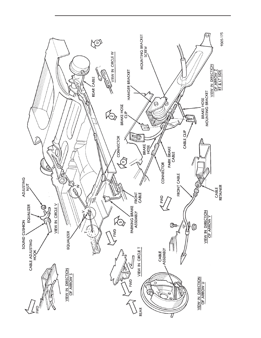
FIG.
2
PARKING
BRAKE
CABLE
ROUTING
AA
AND
AP
BODY
5 - 58
BRAKES
Ä