Chrysler Le Baron, Dodge Dynasty, Plymouth Acclaim. Manual - part 151
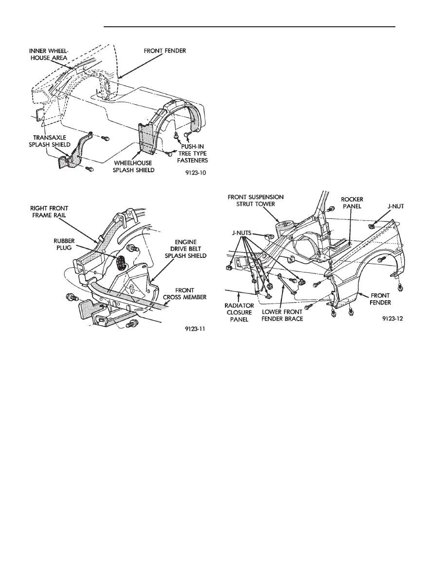
FRONT FENDER
REMOVAL (FIG. 9)
(1) Remove front side marker lamp assembly. Re-
fer to Group 8L, Lamps for instructions.
(2) Remove front bumper as necessary to gain
clearance to remove front fender. Refer to Front
Bumper Removal paragraph in this section.
(3) Remove front wheelhouse splash shield. Refer
to Front Wheelhouse Splash Shield Removal para-
graph of this section.
(4) Remove rocker panel moulding as necessary to
clear front fender. Refer to Body Side Moulding and
Applique Removal paragraph in this section.
(5) Remove bolts holding bottom front fender at
rear of wheel opening.
(6) Remove bolt holding front fender at rear of
wheelhouse.
(7) Remove bolt holding front fender at top of front
door opening.
(8) Remove bolts holding front fender to front
lower brace and under radiator closure panel.
(9) Remove bolts holding front fender to front of
radiator closure panel.
(10) Raise hood and support hood on a suitable
holding device. Mark hinge for installation indexing.
Remove lower hood hinge attaching bolts and sepa-
rate hinge from front fender. Refer to Hood Hinge
Removal paragraph in this section.
(11) Remove bolts holding front fender to inner
wheelhouse along hood opening.
(12) Separate front fender from vehicle.
INSTALLATION
Reverse the preceding operation. Align front fender
to achieve a 4 mm (0.160 in) gap to hood edge and 6
mm (0.240 in) gap to front door edge. All surfaces
across gaps should be flush.
FRONT DOOR TRIM PANEL
DOOR TRIM PANEL WITH POWER WINDOWS
REMOVAL (FIG. 10)
(1) Move glass to down position.
(2) Disconnect battery negative cable.
(3) Using a suitable prying tool, lift upward at
front of power window switch bezel and disengage be-
zel from clip in door panel. Disconnect wire connector
from back of switch.
(4) Remove door latch handle bezel insert. Discon-
nect power door lock switch wire connector, if
equipped. Remove screws holding handle bezel to
trim panel and separate bezel from door.
(5) Remove screw holding armrest pull handle to
door through door latch handle bezel opening.
(6) Remove hidden screw from in carpet at rear
lower corner of trim panel.
(7) Using a suitable trim clip tool, disengage frog
leg clips at the ends and bottom of trim panel. After
all trim clips are loose, push inward at the top of the
trim panel and lift upward to disengage barb fasten-
ers at top of panel. Separate trim from door.
Fig. 7 Front Wheelhouse and Transaxle Splash
Shields
Fig. 8 Engine Drive Belt Splash Shield
Fig. 9 Front Fender Assembly
23 - 14
AA-BODY
Ä