Chrysler Le Baron, Dodge Dynasty, Plymouth Acclaim. Manual - part 110
so that pump housing and case front may be covered
with soapy solution or water. Leaks are sometimes
caused by porosity in the case or pump housing.
If a leak source is located, that part and all associ-
ated seals, O-rings, and gaskets should be replaced
with new parts.
GEARSHIFT LINKAGE ADJUSTMENT
Normal operation of the Park/Neutral Position
Switch provides a quick check to confirm proper
manual linkage adjustment.
Move the selector level slowly upward until it
clicks into the ‘‘P’’ Park notch in the selector gate. If
the starter will operate the ‘‘P’’ position is correct.
After checking ‘‘P’’ position, move selector slowly
toward ‘‘N’’ Neutral position until lever drops in the
‘‘N’’ stop. If the starter will also operate at this point
the gearshift linkage is properly adjusted. If the
starter fails to operate in either position, linkage ad-
justment is required.
CAUTION: When it is necessary to disassemble
linkage cable from levers, which use plastic grom-
mets as retainers, the grommets should be replaced
with new grommets. Use a prying tool to force rod
from grommet in lever, then cut away old grommet.
Use pliers to snap new grommet into lever and rod
into grommet.
(1) Set parking brake.
(2) Place gearshift lever in P (PARK) position.
(3) Loosen clamp bolt on gearshift cable bracket.
(4) Column shift: Insure that preload adjustment
spring engages fork on transaxle bracket.
(5) Pull the shift lever by hand to the front detent
position (PARK) and tighten lock. Tighten screw to
11 N
Im (100 in. lbs.). Gearshift linkage should now
be properly adjusted.
(6) Check adjustment as follows:
(a) Detent position for neutral and drive should
be within limits of hand lever gate stops.
(b) Key start must occur only when shift lever is
in park or neutral positions.
THROTTLE PRESSURE LINKAGE ADJUSTMENT
The throttle pressure cable adjustment is very im-
portant to proper transaxle operation. This adjust-
ment positions a valve which controls shift speed,
shift quality, and part throttle downshift sensitivity.
If the setting is too long, early shifts and slippage be-
tween shifts may occur. If the setting is too short,
shifts may be delayed and part throttle downshifts
may be very sensitive.
CABLE ADJUSTMENT PROCEDURE (4-CYL.)
(1) Perform transaxle throttle pressure cable ad-
justment while engine is at normal operating tem-
perature.
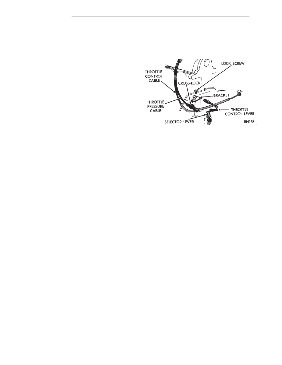
(2) Loosen cable mounting bracket lock screw.
(3) Bracket should be positioned with both bracket
alignment tabs touching the transaxle cast surface.
Tighten lock screw to 12 N
Im (105 in. lbs.) see Fig-
ure 8.
(4) Release cross-lock on the cable assembly (pull
cross-lock upward) see Figure 7.
(5) To insure proper adjustment, the cable must be
free to slide all the way toward the engine, against
its stop, after the cross-lock is released.
(6) Move transaxle throttle control lever fully
clockwise, against its internal stop, and press cross-
lock downward into locked position (Fig. 7).
(7) The adjustment is complete and transaxle
throttle cable backlash was automatically removed.
(8) Test cable freedom of operation by moving the
transaxle throttle lever forward (counterclockwise).
Then slowly release it to confirm it will return fully
rearward (clockwise).
(9) No lubrication is required for any component of
the throttle cable system.
ROD ADJUSTMENT PROCEDURE (6-CYL.)
(1) Perform transaxle throttle pressure cable ad-
justment while engine is at normal operating tem-
perature.
(2) Loosen adjustment swivel lock screw.
(3) To insure proper adjustment, swivel must be
free to slide along flat end of throttle rod so that pre-
load spring action is not restricted. Disassemble and
clean or repair parts to assure free action, if neces-
sary.
(4) Hold transaxle throttle lever firmly toward en-
gine, against its internal stop and tighten swivel lock
screw to 11 N
Im (100 in. lbs.)
(5) The adjustment is finished and linkage back
lash was automatically removed by the preload
spring.
(6) If
lubrication
is
required
see
Lubrication,
Group 0.
Fig. 8 Throttle Pressure Cable—Typical
21 - 46
TRANSAXLE
Ä