Chrysler Le Baron, Dodge Dynasty, Plymouth Acclaim. Manual - part 62
S/C Vacuum Solenoid
A/C Clutch Relay
EGR Solenoid
Auto Shutdown Relay
Radiator Fan Relay
Purge Solenoid
Malfunction Indicator Lamp (Check Engine Lamp)
STATE DISPLAY SENSORS
Connect the DRBII scan tool to the vehicle and ac-
cess the State Display screen. Then access Sensor
Display. The following is a list of the engine control
system functions accessible through the Sensor Dis-
play screen.
Oxygen Sensor Signal
Engine Coolant Temperature
Engine Coolant Temp Sensor
Throttle Position
Minimum Throttle
Battery Voltage
MAP Sensor Reading
Idle Air Control Motor Position
Adaptive Fuel Factor
Barometric Pressure
Min Airflow Idle Spd (speed)
Engine Speed
DIS Sensor Status
Fault #1 Key-On Info
Module Spark Advance
Speed Control Target
Fault #2 Key-on Info
Fault #3 Key-on Info
Speed Control Status
Speed Control Switch Voltage
Charging System Goal
Theft Alarm Status
Map Sensor Voltage
Vehicle Speed
Oxygen Sensor State
MAP Gauge Reading
Throttle Opening (percentage)
Total Spark Advance
CIRCUIT ACTUATION TEST MODE
The circuit actuation test mode checks for proper
operation of output circuits or devices which the pow-
ertrain control module (PCM) cannot internally rec-
ognize. The PCM can attempt to activate these
outputs and allow an observer to verify proper oper-
ation. Most of the tests provide an audible or visual
indication of device operation (click of relay contacts,
spray fuel, etc.). Except for intermittent conditions, if
a device functions properly during testing, assume
the device, its associated wiring, and driver circuit
working correctly.
OBTAINING CIRCUIT ACTUATION TEST
Connect the DRBII scan tool to the vehicle and ac-
cess the Actuators screen. The following is a list of
the
engine
control
system
functions
accessible
through Actuators screens.
Stop All Tests
Ignition Coil #1
Ignition Coil #2
Ignition Coil #3
Fuel Injector #1
Fuel Injector #2
Fuel Injector #3
Fuel Injector #4
Fuel Injector #5
Fuel Injector #6
Idle Air Control Motor Open/Close
Radiator Fan Relay
A/C Clutch Relay
Auto Shutdown Relay
EVAP Purge Solenoid
S/C Servo Solenoids
Generator Field
EGR Solenoid
All Solenoids/Relays
ASD Fuel System Test
Speed Control Vacuum Solenoid
Speed Control Vent Solenoid
THROTTLE BODY MINIMUM AIR FLOW CHECK
PROCEDURE
(1) Warm engine in Park or Neutral until the cool-
ing fan has cycled on and off at least once.
(2) Ensure that all accessories are off.
(3) Shut off engine.
(4) Disconnect the PCV valve hose from the intake
manifold nipple.
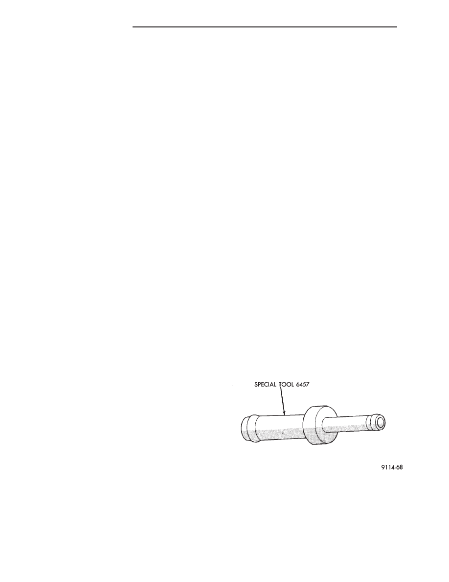
(5) Attach Air Metering Fitting #6457 (0.125 in.
orifice) to the intake manifold PCV nipple (Fig. 2).
(6) Disconnect the 3/16 inch idle purge line from
the throttle body nipple. Cap the 3/16 inch nipple.
(7) Connect DRBII scan tool to vehicle.
(8) Restart the engine. Allow engine to idle for at
least one minute.
(9) Using the DRBII scan tool, access Min. Airflow
Idle Spd.
Fig. 2 Air Metering Fitting #6457
14 - 166
FUEL SYSTEMS
Ä