Daewoo Musso. Manual - part 278


  Index      Daewoo     Daewoo Musso - service repair manual


Search            


Content   ..  276  277  278  279   ..


Daewoo Musso. Manual - part 278


5B-14  MANUAL TRANSMISSION
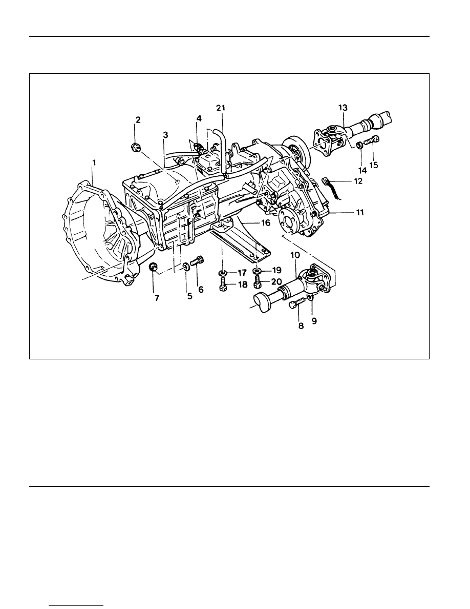
TRANSMISSION

Preceding Work : Removal of the shift control cable

1 Clutch Housing
2 Oil Filler Plug ............................................ 25 Nm
3 Transmission Assembly
4 Back-up Switch
5 Washer
6 Bolt ...................................................... 77-87 Nm
7 Oil Drain Plug ............................................ 25 Nm
8 Bolt ...................................................... 81-89 Nm
9 Washer

10 Front Propeller Shaft

11 Transfer Case Assembly

12 Speedometer Cable
13 Rear Propeller Shaft
14 Washer
15 Bolt ...................................................... 70-80 Nm
16 Cross Member
17 Washer
18 Bolt ...................................................... 21-35 Nm
19 Washer
20 Bolt ...................................................... 62-93 Nm
21 Breather Hose

MANUAL TRANSMISSION  5B-15

Removal & Installation Procedure

1. Disconnect the negative terminal from the battery.

2. Lift up the vehicle and fix it safely.

3. Remove the drain plug from the transmission housing and

drain the oil. Reinstall the drain plug.

Installation Notice

Tightening Torque

25 Nm

4. Disconnect the back-up switch connector.

5. Remove the breather hose.

6. Remove the speedometer connector and other wiring

harnesses and connectors.

5B-16  MANUAL TRANSMISSION

7. Remove the front and rear propeller shafts from the

transfercase.

Installation Notice

Tightening Torque

81 - 89 Nm

70 - 90 Nm

Front

Rear

8. Support the transmission on an suitable jack.

Unscrew the center mounting nuts and each sides
mounting bolts and remove the cross member.

Installation Notice

9. Remove the transmission mounting bolts.

Installation Notice

Tightening Torque (1)

Tightening Torque (2)

21 - 35 Nm

62 - 93 Nm

10. Move the transmission jack backward careful and

disengage the transmission input shaft from the engine.

Remove the transmission.

11. Installation should follow the removal procedure in the

reverse order.

Tightening  Torque

77 - 87 Nm

MANUAL TRANSMISSION  5B-17

UNIT REPAIR

MAJOR UNIT

Preceding Work : Removal of the transmission

Removal of the transfer case

Disassembly Procedure

1. Install the removed transmission into a fixture.

2. Remove the drain plug and drain the oil. Using a 13 mm

wrench, remove the clamp bolt and position the offset lever
in the 3-4 position of neutral.

Notice

Removal of the offset lever in a position other than 3-4 of
neutral will be difficult.

3. Using a pin punch and a hammer, remove the roll pin to

remove the shift lever from the offset lever.

4. Using a 15 mm wrench, remove the 8 bolts from the extension

housing.

5. Separate the extension housing from the case and shift

cover.

Separate the offset lever from the shift.

Notice

Do not remove the offset lever while the extension housing
is still assembled to the case.

6. Remove the offset lever from the extension housing with

the detent ball and spring.

7. Remove the roll pin from either the offset lever or extension

housing.


Content   ..  276  277  278  279   ..