Daewoo Musso. Manual - part 228


  Index      Daewoo     Daewoo Musso - service repair manual


Search            


Content   ..  226  227  228  229   ..


Daewoo Musso. Manual - part 228


4A-6  HYDRAULIC BRAKES
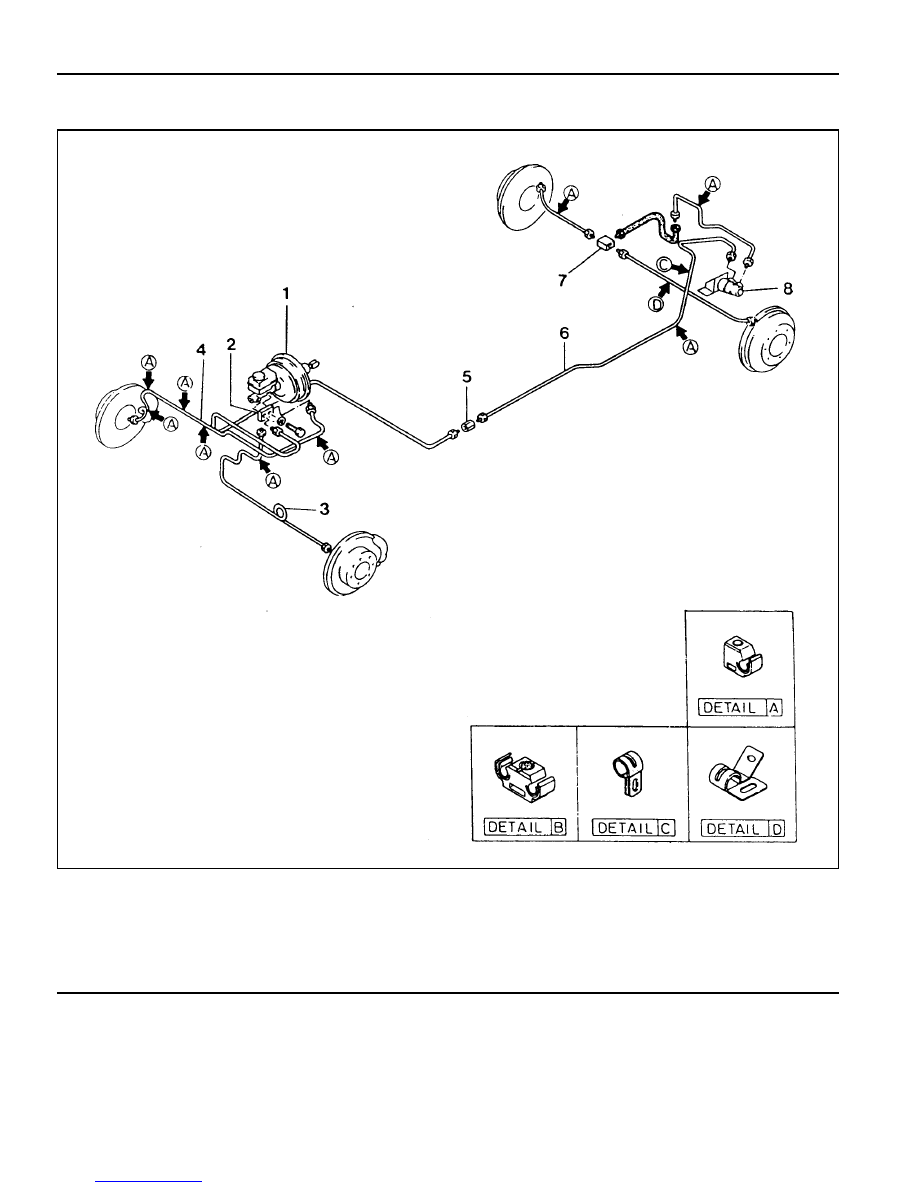
NON-ABS/ABD

1 Actuation Assembly (Booster+TMC)
2 3-way Connector
3 Front Tube (LH)
4 Front Tube (RH)

5 2-way Connector
6 Rear Tube
7 3-way Connector
8 LCRV

HYDRAULIC BRAKES  4A-7

MAINTENANCE AND REPAIR

ON-VEHICLE SERVICE

BLEEDING THE BRAKES

For Master Cylinder Replacement

1. Add oil after master cylinder replacement.

2. Run the engine and depress the brake pedal several times

to build pressure and then keep the pedal fully depressed.

3. Loosen the screws of primary and secondary pipe at the

master cylinder outlets to bleed air.

4. Repeat above step No.3 several times until there are no

more air bubbles.

5. Bleed air in the system at the hydraulic unit outlet pipe and

wheel if pressure building is not enough by depressing the
pedal only after above air bleeding.

For Caliper and Brake Hose Replacement

1. Check the oil level from the oil reservoir and refill if necessary.

2. Run the engine and depress the pedal several times to

build pressure and then keep the pedal fully depressed.

3. Connect a vinyl tube to the caliper breather and prepare a

container to coentain brake oil.

4. Loosen the breather screw until there are no more bubbles.

5. Bleed air in the system at four (4) wheels in order as shown

in right figure if pressure building is not enough by depressing
the pedal after above air bleeding.

Tightening Torque

9 - 14 Nm

Item

Front Bleeder Screw

Rear Bleeder Screw

Notice

l

Do not reuse the bled brake fluid.

l

Always bleed the air after replacing brake fluid or
master cylinder, caliper, brake hose and pipe.

l

Always operate in normal order.

4A-8  HYDRAULIC BRAKES

For Hydraulic Unit Replacement

1. Add oil after hydraulic unit replacement.

2. Run the engine and depress the pedal several times to

build pressure and then keep the  pedal fully depressed.

3. Loosen hydraulic pipe screws at the hydraulic unit outlets

to bleed air.

4. Repeat above step No.3 several times until there are no

more air bubbles.

5. Bleed air in the system from the wheels if pressure building

is not enough by pressing the pedal only after above air
bleeding.

HYDRAULIC BRAKES  4A-9

BRAKE PEDAL

1 Clevis Pin
2 Brake Pedal
3 Stop Lamp Switch
4 Pad
5 Nut ....................................................... 21-35 Nm
6 Yoke Pin
7 Fulcrum Pin

8 Return Spring
9 Pedal  Mounting Bracket

10 Washer

11 Nut ....................................................... 16-32 Nm

12 Bolt ........................................................ 8-18 Nm
13 Stopper Bolt .............................................. Adjust
14 Rubber Pad ........................................... Replace


Content   ..  226  227  228  229   ..