Daewoo Musso. Manual - part 209


  Index      Daewoo     Daewoo Musso - service repair manual


Search            


Content   ..  207  208  209  210   ..


Daewoo Musso. Manual - part 209


2C-8   FRONT SUSPENSION

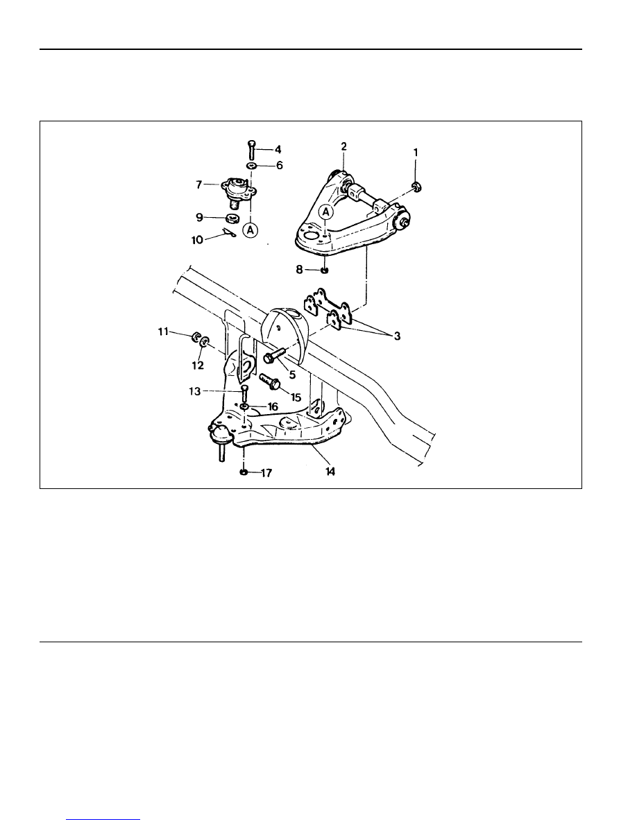
FRONT LOWER AND UPPER ARM

1 Nut ................................................... 120-140 Nm
2 Fulcrum Pin and Upper Arm Assembly
3 Camber/Caster Adjusting Shim
4 Bolt
5 Bolt
6 Washer
7 Upper Arm End
8 Nut ....................................................... 16-22 Nm
9 Castle Nut .......................................... 80-150 Nm

10 Cotter Pin ............................................... Replace

11 Nut ................................................... 150-180 Nm

12 Washer
13 Bolt
14 Lower Arm Assembly and Lower Arm End
15 Bolt
16 Washer
17 Nut ....................................................... 60-80 Nm

Preceding Work : Removal of the torsion bar spring

 Removal of the steering knuckle and drive shaft

 FRONT SUSPENSION  2C-9

Removal & Installation Procedure

1. Remove the shock absorber.

Installation Notice

2. Remove the fulcrum pin mounting bolts and nuts and remove

the upper arm assembly.

Notice

Be careful not to damage or lose the adjusting shims.

Upper

Lower

Distance between the nut end

and the screw end

Tightening Torque

6 - 9 mm

60 - 80 Nm

3. Remove the lower arm mounting bolts (2).

Installation Notice

Tightening  Torque

120 - 140 Nm

4. Pull out the cotter pin from the lower arm ball end assembly

and remove lower arm after loosening the slotted nut.

Installation Notice

Tightening  Torque

150 - 180 Nm

Notice

Replace the cotter pin with new one.

5. Installation should follow the removal precedure in the

reverse order.

Tightening  Torque

120 - 180 Nm

Installation Notice

2C-10   FRONT SUSPENSION

FRONT SHOCK ABSORBER

1 Front Shock Absorber
2 Washer
3 Bush

4 Center Washer
5 Actuator Mounting Bracket
6 Nut ........................................................ 40-60Nm

FRONT SUSPENSION  2C-11

Removal & Installation Procedure

1. Disconnect actuator connector and unscrew bolt and remove

actuator assembly.

Notice

When installing the actuator to the mounting bracket, the
wiring should face the front of the frame.

2. Unscrew the upper nut (6).

Notice

When screwing the nut, actuator contacting surface of the
mounting bracket and rod end should be 0.5 - 1.5mm.

3. Remove the mounting bracket (5).

Notice

When installing the bracket, it should be vertical to the frame
side member.

4. Remove the bush and check for damage and replace if

necessary.

5. Unscrew shock absorber lower bolt and nut and remove

the shock absorber.

Notice

Shock absorber is filled with gas, never attempt to cut or
heat.

6. Installation should follow the removal procedure in the

reverse order.


Content   ..  207  208  209  210   ..