Daewoo Musso. Manual - part 189


  Index      Daewoo     Daewoo Musso - service repair manual


Search            


Content   ..  187  188  189  190   ..


Daewoo Musso. Manual - part 189


1F3-36  OM600 ENGINE CONTROLS

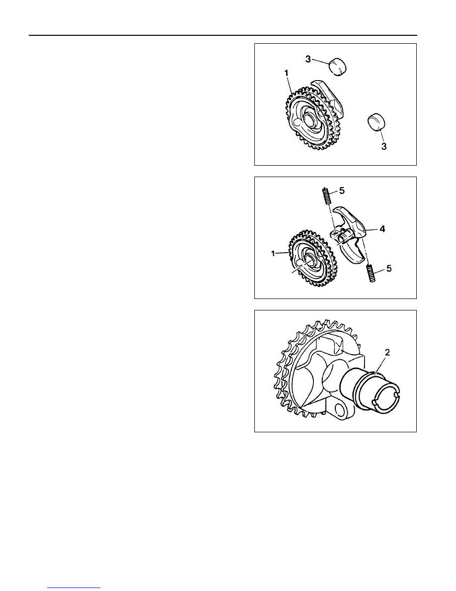
Disassembly & Assembly

1. Remove the governor weights (3).

2. Pull out the compression springs (5) and cam sprocket (1)

from the segment flange (4).

3. Knock out the bushing with a proper drift.

4. Installation should follow the removal procedure in the

reverse order.

OM600 ENGINE CONTROLS  1F3-37

START OF DELIVERY TEST (POSITION SENSOR, RIV METHOD)

1 Position Sensor
2 Battery
3 Fuel Injection Pump

4 Seal ....................................................... Replace
5 Screw Plug ................................................. 30Nm

Service Data

Start of Delivery (RIV)

ATDC 14° - 16°

1F3-38  OM600 ENGINE CONTROLS

Tools Required

617 589 08 21 00  Position Sensor

Test Procedure

1. Remove the screw plug (5) and seal (4) and collect oil in a

suitable vessel.

2. Install the position sensor (1) into the governor housing of

the injection pump to be the guide pin of the position sensor
facing up.

3. Connect the battery terminal of position sensor (1) to positive

terminal (+) of battery.

Position Sensor 617 589 08 21 00

4. Rotate the crankshaft by hand (in direction of engine rotation)

until the lamp ‘B’ lights up. Rotate the crankshaft carefully
further until both lamps ‘A and B’ come on. In this position,
check the Rl value  on the crankshaft vibration damper.

Notice

If only lamp ‘A’ lights up, repeat the test and if out of
specification, adjust start of delivery.

Specification

ATDC 14° - 16°

OM600 ENGINE CONTROLS  1F3-39

Digital Tester, RIV Method

(Connection Diagram for Testers Without Adapter)

1 Fuel Injection Pump
2 Rl Sensor
3 Digital Tester

4 TDC Pulse Sender Unit
5 Battery


Content   ..  187  188  189  190   ..