Daewoo Matiz (2003 year). Manual - part 274


  Index      Daewoo     Daewoo Matiz - service repair manual 2003 year


Search            


Content   ..  272  273  274  275   ..


Daewoo Matiz (2003 year). Manual - part 274


9P – 12  DOORS

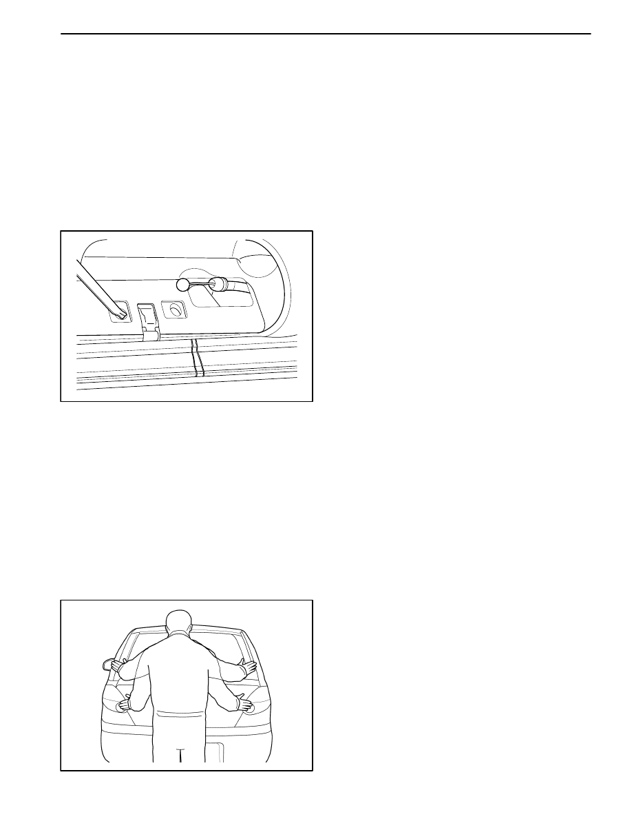
The tailgate lock striker consists of a striker with two
screws that are threaded into a tapped, floating cage
plate located in the appropriate body pillar. This floating
cage plate allows the striker to be easily adjusted in or
out and up or down. The tailgate is secured in the closed
position when the tailgate lock fork snaps over and en-
gages the striker.

D109C578

Fore/Aft or In/Out Adjustment

An adjustment of the striker in the fore and aft or in and
out directions may be necessary for a number of reasons:
vehicle frame damage as the result of a collision, installa-
tion of new tailgate weatherstripping, customer com-
plaints of excessive windnoise, or difficulty in opening or
closing the tailgate. In order to adjust the tailgate striker in
an fore and aft or in and out direction, perform the follow-
ing procedure:

1. The tailgate must be properly aligned.

2. Loosen the striker screws.

3. The floating cage plate can be moved slightly using

the ends of the striker screws. Move the floating cage
plate to the desired position.

Notice: It is important to use a flat-end rotary file in or-
der not to damage the tapped floating cage plate. The
striker screws and the tapped floating cage plate are im-
portant attaching parts that could affect the performance
of vital components and systems.

D109C579

4. If proper adjustment requires that the floating cage plate

be moved more than is possible, use an electric hand
drill and a 3/8- inch rotary file with a flat head in order to
enlarge the body opening in the direction required.

5. Tighten the striker screws to the correct position.

6. Perform the up/down adjustment. Refer to “Up and

Down Adjustment” in this section.

DOORS  9P – 13

D19C580A

Up and Down Adjustment

1. The tailgate must be properly aligned.

2. Close the tailgate until the lock fork contacts the strik-

er.

3. Stand next to the tailgate opening and move the tail-

gate slowly up and down, just touching the striker
each time.

D109C581

4. The alignment of the lock fork and the striker can be

easily seen. The lock fork should be perpendicular to
and fall near the middle of the striker. The lock fork
should fall near the middle of the striker between the
rear body pillar and the end of the striker.

D109C582

5. If a up and down adjustment is required, use the fol-

lowing steps:

D

Remove the striker screws (1).

D

Remove the spacer in order to move the striker to-
ward the down of the vehicle (2).

D

Add a 2 mm (0.08 inch) spacer in order to move
the striker toward the up of the vehicle.

D

Install the striker screws.

D19C583A

FRONT DOOR LOCK

Removal Procedure

1. Disconnect the negative battery cable if equipped

with the central door lock system.

2. Remove the seal trim. Refer to “Door Seal Trim” in

this section.

3. Disconnect the outside door handle rod from the door

lock.

a. Outside door handle rod.

b. Key rod.

9P – 14  DOORS

D109C584

4. Remove the front door lock.

D

Remove the screws (1).

D

Remove the front door lock (2).

Important: Disconnect the actuator connector, if
equipped with the central door lock system.

D109C585

Installation Procedure

Notice:  Dissimilar metals in direct contact with each
other may corrode rapidly. Make sure to use the correct
fasteners to prevent premature corrosion.

1. Install the front door lock with screws.

Important: Connect the actuator connector if equipped
with the central door lock system.

2. Connect the outside door handle rod and the key rod

to the door lock.

3. Install the seal trim. Refer to “Door Seal Trim” in this

section.

4. Connect the negative battery cable, if equipped with

the central door lock system.

D109C566

CHILDPROOF REAR DOOR LOCK

Removal Procedure

1. Disconnect the negative battery cable if equipped

with the central door lock system.

2. Remove the door trim panel. Refer to Section 9G, In-

terior Trim.

3. Remove the door seal trim. Refer to “Door Seal Trim”

in this section.
a. Door seal trim.
b. Door pocket handle bracket.

Important: In case of the deluxe type, remove the seal
trim after removing the door pocket handle bracket.

D109C567

4. Remove the guide piece.

D

Remove the screw (1).

D

Remove the guide piece (2).

DOORS  9P – 15

D109C583

5. Disconnect the outside door handle rod from the door

lock.

a. Outside door handle rod.

D109C586

6. Disconnect the door lock from the vehicle.

D

Remove the screws (1).

D

Remove the door lock (2).

Important:  Disconnect the actuator connector if
equipped with the central door lock system.

D109C587

Installation Procedure

Notice:  Dissimilar metals in direct contact with each
other may corrode rapidly. Make sure to use the correct
fasteners to prevent premature corrosion.

1. Install the rear door lock with the screws.

Important: Connect the actuator connector if equipped
with the central door lock system.

2. Connect the outside door handle rod to the door lock.

3. Install the guide rail with the screw.

4. Install the seal trim. Refer to “Door Seal Trim” in this

section.

5. Install the door trim panel. Refer to Section 9G, Interi-

or Trim.

6. Connect the negative battery cable if equipped with

the central door lock system.


Content   ..  272  273  274  275   ..