Daewoo Matiz (2003 year). Manual - part 110
FRONT SUSPENSION 2C – 5
DIAGNOSTIC INFORMATION AND PROCEDURES
STRUT DAMPENER
A strut dampener is basically a shock absorber. However, strut dampeners are easier to extend and retract by hand
than are shock absorbers. Strut dampeners are used only on the front in most vehicles, including this vehicle. Shock
absorbers are used on the rear wheels.
ÁÁÁÁÁÁÁÁÁÁ
ÁÁÁÁÁÁÁÁÁÁ
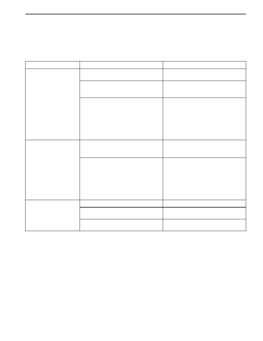
Condition
ÁÁÁÁÁÁÁÁÁÁÁÁÁ
ÁÁÁÁÁÁÁÁÁÁÁÁÁ
Probable cause
ÁÁÁÁÁÁÁÁÁÁÁÁÁÁ
ÁÁÁÁÁÁÁÁÁÁÁÁÁÁ
Correction
Struts Seem Weak
D
Improper tire pressures.
D
Adjust the tire pressures to the speci-
fications on the tire placard.
D
Abnormal load conditions.
D
Consult with the owner to confirm the
owner’s understanding of normal load
conditions.
D
Improper compression and rebound
effectiveness of the strut dampener.
D
Quickly push down and then lift up on
the corner of the bumper nearest the
strut dampener being tested.
D
Compare the compression and re-
bound with those of a similar vehicle
that has an acceptable ride quality.
D
Replace the strut dampener, if need-
ed.
Struts are Noisy
D
Loose or damaged mountings.
D
Tighten the strut dampener.
D
Replace the strut dampener if need-
ed.
D
Improper compression and rebound
effectiveness of the strut dampener.
D
Quickly push down and then lift up on
the corner of the bumper nearest the
strut dampener being tested.
D
Compare the compression and re-
bound with those of a similar vehicle
that has an acceptable ride quality.
D
Replace the strut dampener, if need-
ed.
Leaks
D
A slight trace of fluid.
D
The strut dampener is OK.
D
Leaks of the seal cover on the fully
extended strut.
D
Replace the strut dampener.
D
Excessive leaks of fluid on the strut
dampener.
D
Replace the strut dampener.
BALL JOINT AND KNUCKLE
Ball Joint Inspection
1. Raise the front of the vehicle to allow the front sus-
pension to hang free.
2. Grasp the tire at the top and the bottom.
3. Move the top of the tire in an in-and-out motion.
4. Look for any horizontal movement of the knuckle rela-
tive to the control arm.
5. Control arms assembly must be replaced if the follow-
ing conditions exist:
D
The joint is loose.
D
The ball seal is cut.
D
The ball stud is disconnected from the knuckle.
D
The ball stud is loose at the knuckle.
D
The ball stud can be twisted in its socket with finger
pressure.
Ball Stud Inspection
Make sure to check the tightness of the ball stud in the
knuckle boss during each inspection of the ball joint.
One way to inspect the ball stud for wear is to shake the
wheel and feel for movement of the stud end or the cas-
tellated nut at the knuckle boss.
Another way to inspect the ball stud for wear is to check
the fastener torque at the castellated nut. A loose nut can
indicate a stressed stud or a hole in the knuckle boss.
Worn or damaged ball joints and knuckles must be re-
placed.