Daewoo Matiz (2003 year). Manual - part 87


  Index      Daewoo     Daewoo Matiz - service repair manual 2003 year


Search            


Content   ..  85  86  87  88   ..


Daewoo Matiz (2003 year). Manual - part 87


1F – 258  ENGINE CONTROLS

MAA1F320

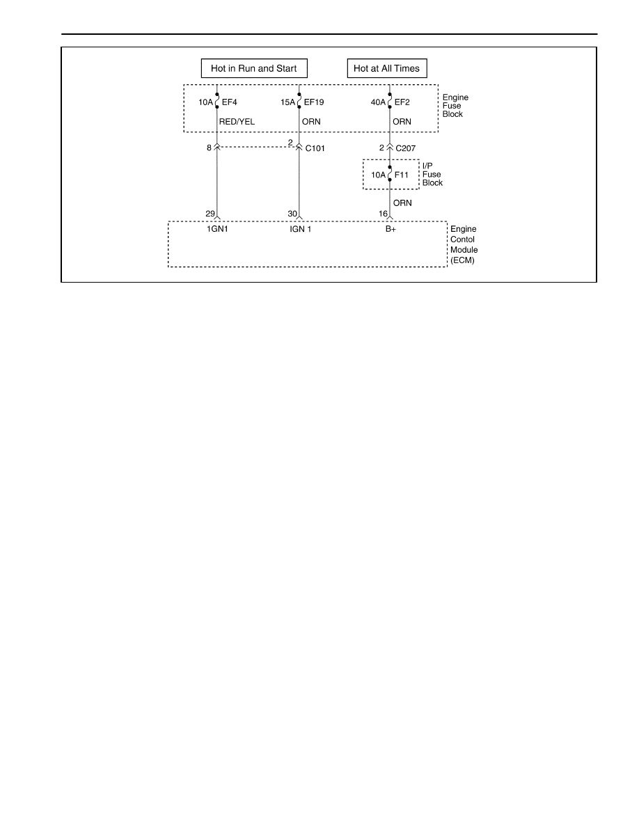
DIAGNOSTIC TROUBLE CODE (DTC) – P0562 SYSTEM VOLTAGE(ENGINE

SIDE) TOO LOW

Circuit Description

The engine control module (ECM) monitors the ignition
voltage on the ignition feed circuit to terminal 7 at the
ECM. A system voltage Diagnostic Trouble Code (DTC)
sill set whenever the voltage is below a calibrated value.

Conditions for Setting the DTC

D

Ignition ON.

D

Main relay is ON.

D

The ignition voltage is less than 11.5 volt.

D

The main relay voltage is less than 5.0V or higher
than 26V during 7.6 seconds.

Action Taken When the DTC Sets

D

The Malfunction Indicator Lamp (MIL) will not illumi-
nate.

D

The ECM will store conditions which were present
when the DTC was set as Failure Records data only.

D

This information will not be stored in the Freeze
Frame data.

Conditions for Clearing the MIL/DTC

D

A history DTC will clear after 40 consecutive warm-up
cycles without a fault.

D

DTC(s) can be cleared by using the scan tool.

Diagnostic Aids

An Intermittent problem may be caused by a poor con-
nection, rubbed through wire insulation, or wire that is
broken inside the insulation.

Any circuitry, that is suspected as causing the com-
plaint, should be thoroughly checked for the following
conditions.

D

Backed-out terminals

D

Improper mating

D

Broken locks

D

Improperly formed

D

Damaged terminals

D

Poor terminals to wire connection

D

Physical damage to the wiring harness

ENGINE CONTROLS  1F – 259

DTC P0562 – System Voltage (Engine Side) Too Low

Step

Action

Value(s)

Yes

No

1

Perform an On-Board Diagnostic (EOBD) System
Check.
Is the system check complete?

Go to Step 2

Go to

“On-Board
Diagnostic

System Check”

2

1. Install a scan tool and clear the Diagnostic

Trouble Codes (DTCs).

2. Start the engine and raise the engine speed to

the specified value.

3. Load the electrical system by turning on the

headlights, high blower motor, etc.

Is the ignition voltage less than the specified value?

1,400rpm 10V

Go to Step 3

Go to Step 8

3

1. With the engine still running at the specified

value.

2. Using a digital voltmeter(DVM), measure the

battery voltage at the battery.

Is the battery voltage greater than the specified
value?

1,400rpm 12V

Go to Step 4

Go to

“Diagnostic

Aids”

4

1. Turn the ignition switch to LOCK.
2. Disconnect the engine control module(ECM)

connector at the ECM.

3. Turn the Turn the ignition switch to ON with the

engine OFF.

4 Using a DVM, measure the ignition voltage at the

ignition feed circuit, terminal 29.

Is the ignition voltage greater than the specified
value?

10V

Go to Step 5

Go to Step 6

5

Check for a malfunctioning connection at the ECM
harness terminals and repair as necessary.
Is a repair necessary?

Go to Step 8

Go to Step 7

6

Repair the poor connection (high resistance) in the
ignition feed circuit.
Is the repair complete?

Go to Step 8

7

Replace the ECM.
Is the replacement complete?

Go to Step 8

8

1 Using the scan tool, clear the DTCs.
2. Start the engine and idle at normal operating

temperature.

3. Operate the vehicle within the conditions for

setting this DTC ad specified in the supporting
text.

Does the scan tool indicate that this diagnostic has
run and passed?

Go to Step 9

Go to Step 2

9

Check if any additional DTCs are set.
Are any DTCs displayed that have not been
diagnosed?

Go to

applicable DTC

table

System OK

1F – 260  ENGINE CONTROLS

MAA1F320

DIAGNOSTIC TROUBLE CODE (DTC) – P0563 SYSTEM VOLTAGE (ENGINE

SIDE) TOO HIGH

Circuit Description

The engine control module (ECM) monitors the ignition
voltage on the ignition feed circuit to terminal 7 at the
ECM. A system voltage Diagnostic Trouble Code (DTC)
sill set whenever the voltage is below a calibrated value.

Conditions for Setting the DTC

D

Ignition ON.

D

The ignition voltage is greater than 16 volt.

Action Taken When the DTC Sets

D

The Malfunction Indicator Lamp (MIL) will not illumi-
nate.

D

The ECM will store conditions which were present
when the DTC was set as Failure Records data only.

D

This information will not be stored in the Freeze
Frame data.

Conditions for Clearing the MIL/DTC

D

A history DTC will clear after 40 consecutive warm-up
cycles without a fault.

D

DTC(s) can be cleared by using the scan tool.

D

Disconnecting the ECM battery feed for more than 10
seconds.

Diagnostic Aids

An Intermittent problem may be caused by a poor con-
nection, rubbed through wire insulation, or wire that is
broken inside the insulation.

Any circuitry, that is suspected as causing the com-
plaint, should be thoroughly checked for the following
conditions.

D

Backed-out terminals

D

Improper mating

D

Broken locks

D

Improperly formed

D

Damaged terminals

D

Poor terminals to wire connection

D

Physical damage to the wiring harness

ENGINE CONTROLS  1F – 261

DTC P0563 – System Voltage (Engine Side) Too High

Step

Action

Value(s)

Yes

No

1

Perform an On-Board Diagnostic (EOBD) System
Check.
Is the system check complete?

Go to Step 2

Go to

“On-Board
Diagnostic

System Check”

2

1. Install a scan tool and clear the Diagnostic

Trouble Codes (DTCs).

2. Start the engine and raise the engine speed to

the specified value.

3. Load the electrical system by turning on the

headlights, high blower motor, etc.

Is the ignition voltage less than the specified value?

1,400rpm 10V

Go to Step 3

Go to Step 8

3

1. With the engine still running at the specified

value.

2. Using a digital voltmeter(DVM), measure the

battery voltage at the battery.

Is the battery voltage greater than the specified
value?

1,400rpm 12V

Go to Step 4

Go to

“Diagnostic

Aids”

4

1. Turn the ignition switch to LOCK.
2. Disconnect the engine control module(ECM)

connector at the ECM.

3. Turn the Turn the ignition switch to ON with the

engine OFF.

4. Using a DVM, measure the ignition voltage at the

ignition feed circuit, terminal 29.

Is the ignition voltage greater than the specified
value?

10V

Go to Step 5

Go to Step 6

5

Check for a malfunctioning connection at the ECM
harness terminals and repair as necessary.
Is a repair necessary?

Go to Step 8

Go to Step 7

6

Repair the poor connection (high resistance) in the
ignition feed circuit.
Is the repair complete?

Go to Step 8

7

Replace the ECM.
Is the replacement complete?

Go to Step 8

8

1. Using the scan tool, clear the DTCs.
2. Start the engine and idle at normal operating

temperature.

3. Operate the vehicle within the conditions for

setting this DTC ad specified in the supporting
text.

Does the scan tool indicate that this diagnostic has
run and passed?

Go to Step 9

Go to Step 2

9

Check if any additional DTCs are set.
Are any DTCs displayed that have not been
diagnosed?

Go to

applicable DTC

table

System OK


Content   ..  85  86  87  88   ..