DAF 95XF. Manual - part 609
8
HYDRAULIC LIFTING GEAR
General
2-2
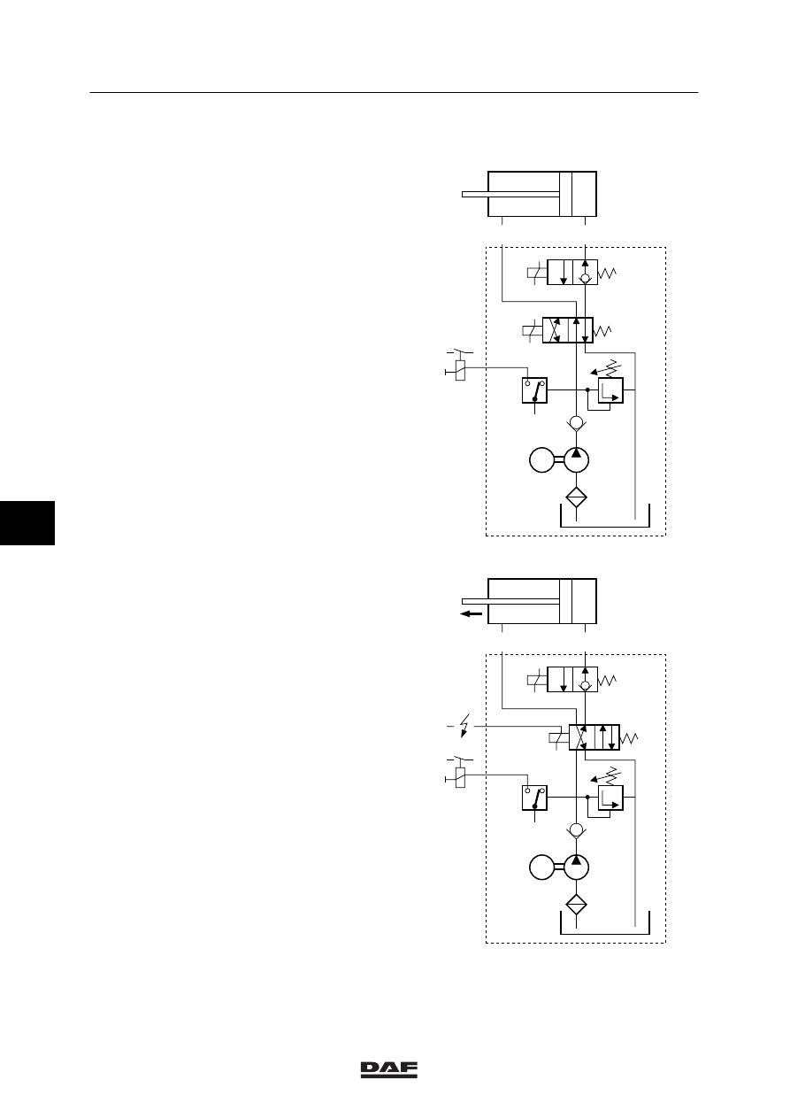
2.2 SYSTEM DESCRIPTION, HYDRAULIC PART
The hydraulic part of the trailing-axle lifting gear
is composed of a pump unit and two parallel,
double-acting cylinders. Both when lifting and
lowering the trailing axle, the pump will deliver
oil to the cylinders.
The pump unit is composed of a gear pump
which is driven by an electric motor, a plastic
reservoir and a valve block.
The valve block is equipped with the following
valves: a non-return valve (6), the
pressure-relief valve (2), the 4/2 magnetic valve
“lift trailing axle” (3) and the 2/2 valve “lower
trailing axle” (4).
The valve block is also equipped with a pressure
switch (1).
When the lifting gear is not being operated, both
magnetic valves (3 and 4) will be deactivated.
Lifting
-
When the lifting-gear control switch is
placed in the “lifting” position, the pump
relay and the 4/2 magnetic valve (3) are
activated.
The activated magnetic valve (3) connects
the pump delivery side to the space behind
the pistons in the cylinders. The space in
front of the pistons is connected to the
reservoir.
-
The pump relay activates the pump, after
which oil is carried to the cylinders through
line connection B. Due to the pressure
build-up from the cylinders, the piston rods
are pushed from the cylinders, thus lifting
the trailing axle via the lever effect.
A
B
M
4
3
2
6
1
A8 00 257
A
B
M
4
3
2
6
1
A8 00 258
ǹ 0001
6