Chrysler Pacifica Hybrid (2022 year). Manual in english - page 21
 

  Index      Manuals     Chrysler Pacifica Hybrid (2022 year). Manual in english


Search            copyright infringement  


Content      ..     19      20      21      22     ..


Chrysler Pacifica Hybrid (2022 year). Manual in english - page 21


330

SERVICING AND MAINTENANCE


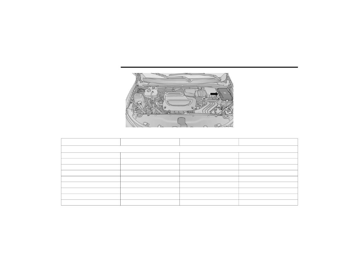
Power Distribution Center Location

Cavity

Cartridge Fuse

Blade Fuse

Description

*If Equipped

F06

Not Populated

F07

25 Amp Clear

Ignition Coil / Fuel Injector

F08

Not Populated

F09

25 Amp Clear

Amplifier / Active Noise Control *

F10

Not Populated

F11

Not Populated

F12

5 Amp Tan

Battery Sensor (IBS) 

F13

10 Amp Red

ECM (S) *

F14

10 Amp Red

ECM

SERVICING AND MAINTENANCE

331

F15

40 Amp Green

CBC / Power Locks

F16

20 Amp Yellow

ECM

F17

30 Amp Pink

Starter

F18

40 Amp Green

CBC / EXT LIGHTS

F19

25 Amp Clear

2nd Row Folding Seats Solenoid LT *

F20

10 Amp Red

A/C Compressor Clutch

F21

25 Amp Clear

2nd Row Folding Seat Solenoid RT *

F22

Not Populated

F23

Not Populated

F24

20 Amp Yellow

RR Wiper

F25

10 Amp Red

Hands Free Dr Mod / Active Grille 

Shutter / Pwr Mirror / VRM

F26

40 Amp Green

Front HVAC Blower Motor

F27

25 Amp Clear

RR Slide Door Module-RT *

F28

10 Amp Red

Diagnostic Port / USB+(IP) / Video 

USB Port / Overhead DVD 

Player(Aftermarket)

F29

Not Populated

F30

15 Amp Blue

Media HUB / Power Lumbar *

F31

Not Populated

F32

20 Amp Blue

ECM

Cavity

Cartridge Fuse

Blade Fuse

Description

*If Equipped

8

332

SERVICING AND MAINTENANCE


F33

30 Amp Pink

Power Liftgate Module *

F34

25 Amp Clear

RR Door Module-LT *

F35

25 Amp Clear

Sunroof *

F36

Not Populated

F37

40 Amp Green

CBC / Exterior Lights

F38

60 Amp Yellow

Vacuum Cleaner *

F39

25 Amp Clear

Rear HVAC Blower Motor

F40

Not Populated

F41

Not Populated

F42

40 Amp Green

Folding Seat Module *

F43

20 Amp Yellow

Fuel Pump Motor

F44

30 Amp Pink

CBC / Interior Lights

F45

30 Amp Pink

Power Inverter *

F46

30 Amp Pink

Driver Door Module

F47

30 Amp Pink

Passenger Door Module

F48

Not Populated

F49

25 Amp Clear

RR Sliding Door Module-LT *

F50

25 Amp Clear

RR Door Module-RT *

F51

30 Amp Pink

Front Wiper

F52

30 Amp Pink

Brake Vacuum Pump

Cavity

Cartridge Fuse

Blade Fuse

Description

*If Equipped

SERVICING AND MAINTENANCE

333

F53

Not Populated

F54

40 Amp Green

ESP-ECU And Valves

F55

15 Amp Blue

Radio Frequency HUB/ Keyless 

Ignition System (KIN) / ESL / DVD

F56

10 Amp Red

Front and Rear HVAC Control 

Module / Occupant Classification 

Module (OCM) / Electronic Steering 

Lock (ESL) / ESP / ESC

F57

Not Populated

F58

10 Amp Red

Drive Train Control Mod / Power 

Transfer Unit *

F59

30 Amp Pink

Trailer Tow Receptacle *

F60

20 Amp Yellow

Rear Cargo Pwr Outlet

F61

20 Amp Yellow

Trailer Tow Right Stop/Turn *

F62

20 Amp Yellow

Power Transfer Unit *

F63

20 Amp Yellow

Trailer Tow Left Stop/Turn *

F64

15 Amp Blue

RT HID Headlamp *

F65

Not Populated

F66

15 Amp Blue

Cluster

F67

10 Amp Red

Haptic Lane Feedback Module

(HALF) / Parktronics System (PTS)/

Drivers Assist System Module (DASM)

Cavity

Cartridge Fuse

Blade Fuse

Description

*If Equipped

8

334

SERVICING AND MAINTENANCE


F68

Not Populated

F69

Not Populated

F70

Not Populated

F71

20 Amp Yellow

Horn

F72

10 Amp Red

Heated Mirror *

F73

30 Amp Pink

Rear Defroster

F74

20 Amp Blue

Trailer Tow Backup Lights*

F75

5 Amp Tan

Overhead Console / RR Center Stack

F76

20 Amp Yellow

Uconnect / Center Display / 

Telematics

F77

10 Amp Red

RR Entertainment / Media HUB / 

USB(S) / Rain Sensor / Sunroof / RR 

View Mirror/ Overhead DVD Player / 

INT Monitoring Camera / Wireless 

Charging Pad

F78

15 Amp Blue

TCM (ZF) / E-Shifter / Cluster

F79

10 Amp Red

ICS / HVAC / SCCM/ EPB SW

F80

Not Populated

F81

Not Populated

F82

Not Populated

Cavity

Cartridge Fuse

Blade Fuse

Description

*If Equipped

SERVICING AND MAINTENANCE

335

F83

20 Amp Blue


TT Park Lights *

30 Amp Pink

Headlamp Washer Pump *

F84

30 Amp Pink

Drive Train Control MOD *

F85

20 Amp Yellow

Cigar Lighter

F86

Not Populated

F87

Not Populated

F88

20 Amp Yellow

Front Heated Seats *

F89

20 Amp Yellow

Rear Heated Seats *

F90

Not Populated

F91

15 Amp Blue

Front Ventilated Seats/Heated 

Steering Wheel *

F92

5 Amp Tan

Security Gateway

F93

Not Populated

Cavity

Cartridge Fuse

Blade Fuse

Description

*If Equipped

8

336

SERVICING AND MAINTENANCE


30 Amp mini fuse is substituted for 25 Amp Circuit Breaker.

F94

40 Amp Green

ESC Motor Pump

F95A

10 Amp Red

USB Charge Port — ACC/RUN

F95B

10 Amp Red

Selectable Fuse Location – USB IP 

(Direct) B+

F96

10 Amp Red

Airbag

F97

10 Amp Red

Airbag

F98

15 Amp Blue

Left HID Headlamp *

F99

30 Amp Pink

Trailer Tow Elect Brake Module *

F100

10 Amp Red

Headlamp Level / RR Camera / 

Blindspot / Humidity SNSR / In Car 

Temp SNSR / Headlamp SW *

Circuit Breakers

CB1

25 Amp

Power Seats (Driver)

CB2

25 Amp *

Power Seats (Pass)

CB3

25 Amp

FRT PWR Window W/O Door Nodes + 

RR PWR Window Lockout

Cavity

Cartridge Fuse

Blade Fuse

Description

*If Equipped

SERVICING AND MAINTENANCE

337

B

ULB

 R

EPLACEMENT


Replacement Bulbs, Names, And Part Numbers   

In the instance a bulb needs to be replaced, this section includes bulb description and replacement part numbers.

NOTE:

Your vehicle is equipped with LED lamps. For replacement of LED lamps, see an authorized dealer.
Interior Bulbs — Halogen

NOTE:

Your vehicle is equipped with LED lamps. For 

replacement of LED lamps, see an authorized 

dealer.
Exterior Bulbs — Halogen

Interior Bulbs

Lamps

Bulb Number

Visor Vanity Lamps

6501966

Exterior Bulbs

Lamps

Bulb Number

Front Turn Signal Lamp

WY21W / 7440NA

Front Side Marker Lamp

W3W / 2821

Rear Side Marker Lamp

W3W / 2821

8

338

SERVICING AND MAINTENANCE


Replacing Exterior Bulbs

FRONT TURN SIGNAL LAMP  

See the following steps to replace:
1. Open the hood.
2. Twist the front turn signal lamp socket 

assembly counterclockwise, and then remove 

the front turn signal lamp assembly from the 

lamp housing.

Front Turn Signal Lamp Socket

3. Pull the bulb out of the socket and insert the 

replacement bulb.

4. Install the front turn signal lamp socket 

assembly into the housing, and rotate the front 

turn signal lamp socket clockwise to lock it in 

place.

FRONT AND REAR SIDE MARKER LAMPS      

See the following steps to replace:
1. Remove the three fasteners from the inner 

wheel liner and carefully peel back liner for 

access.

Inner Wheel Liner Fasteners

2. Firmly grab the front side marker lamp socket 

and rotate a quarter turn counterclockwise to 

remove it from the lamp assembly.

Front Side Marker Lamp Bulb Removal

3. Remove bulb from the front side marker lamp 

socket and replace with a new bulb.

4. Install front side marker lamp socket in lamp 

assembly and rotate a quarter turn clockwise 

to lock into place.

5. Position the inner wheel liner in place and 

install the three fasteners.

SERVICING AND MAINTENANCE

339

TIRES 

T

IRE

 S

AFETY

 I

NFORMATION


Tire safety information will cover aspects of the 

following information: Tire Markings, Tire 

Identification Numbers, Tire Terminology and 

Definitions, Tire Pressures, and Tire Loading.

Tire Markings 

Tire Markings

NOTE:

P (Passenger) — Metric tire sizing is based on US 

design standards. P-Metric tires have the letter 

“P” molded into the sidewall preceding the size 

designation. Example: P215/65R15 95H.

European — Metric tire sizing is based on Euro

-

pean design standards. Tires designed to this 

standard have the tire size molded into the side

-

wall beginning with the section width. The letter 

"P" is absent from this tire size designation. 

Example: 215/65R15 96H.

LT (Light Truck) — Metric tire sizing is based on 

US design standards. The size designation for 

LT-Metric tires is the same as for P-Metric tires 

except for the letters “LT” that are molded into 

the sidewall preceding the size designation. 

Example: LT235/85R16.

Temporary spare tires are designed for tempo

-

rary emergency use only. Temporary high pres

-

sure compact spare tires have the letter “T” or 

“S” molded into the sidewall preceding the size 

designation. Example: T145/80D18 103M.

High flotation tire sizing is based on US design 

standards and it begins with the tire diameter 

molded into the sidewall. 

Example: 31x10.5 R15 LT.

1 — US DOT Safety Standards Code 

(TIN)
2 — Size Designation
3 — Service Description
4 — Maximum Load
5 — Maximum Pressure
6 — Treadwear, Traction and Tempera

-

ture Grades

8

340

SERVICING AND MAINTENANCE


TIRE SIZING CHART 

EXAMPLE:

Example Size Designation: P215/65R15XL 95H, 215/65R15 96H, LT235/85R16C, T145/80D18 103M, 31x10.5 R15 LT
P = Passenger car tire size based on US design standards, or
"....blank...." = Passenger car tire based on European design standards, or
LT = Light truck tire based on US design standards, or
T or S = Temporary spare tire or
31 = Overall diameter in inches (in)
215, 235, 145 = Section width in millimeters (mm)
65, 85, 80 = Aspect ratio in percent (%) 

Ratio of section height to section width of tire, or

10.5 = Section width in inches (in)
R = Construction code 

"R" means radial construction, or

"D" means diagonal or bias construction

15, 16, 18 = Rim diameter in inches (in)
Service Description:
95 = Load Index 

A numerical code associated with the maximum load a tire can carry

H = Speed Symbol 

A symbol indicating the range of speeds at which a tire can carry a load corresponding to its load index under certain operating conditions

The maximum speed corresponding to the speed symbol should only be achieved under specified operating conditions (i.e., tire pressure, vehicle loading, 

road conditions, and posted speed limits)

SERVICING AND MAINTENANCE

341

Tire Identification Number (TIN)

The TIN may be found on one or both sides of the tire; however, the date code may only be on one side. Tires with white sidewalls will have the full TIN, including 

the date code, located on the white sidewall side of the tire. Look for the TIN on the outboard side of black sidewall tires as mounted on the vehicle. If the TIN is 

not found on the outboard side, then you will find it on the inboard side of the tire.

Load Identification:
Absence of the following load identification symbols on the sidewall of the tire indicates a Standard Load (SL) tire:

XL = Extra load (or reinforced) tire, or

LL = Light load tire or

C, D, E, F, G = Load range associated with the maximum load a tire can carry at a specified pressure

Maximum Load – Maximum load indicates the maximum load this tire is designed to carry
Maximum Pressure – Maximum pressure indicates the maximum permissible cold tire inflation pressure for this tire

EXAMPLE:

EXAMPLE:

DOT MA L9 ABCD 0301
DOT = Department of Transportation 

This symbol certifies that the tire is in compliance with the US Department of Transportation tire safety standards and is approved for highway use

MA = Code representing the tire manufacturing location (two digits)
L9 = Code representing the tire size (two digits)
ABCD = Code used by the tire manufacturer (one to four digits)

8

342

SERVICING AND MAINTENANCE


Tire Terminology And Definitions

03 = Number representing the week in which the tire was manufactured (two digits) 

03 means the 3rd week

01 = Number representing the year in which the tire was manufactured (two digits) 

01 means the year 2001

Prior to July 2000, tire manufacturers were only required to have one number to represent the year in which the tire was manufactured. Example: 031 could 

represent the 3rd week of 1981 or 1991

Term

Definition

B-pillar

The vehicle B-pillar is the structural member of the body located behind the front door.

Cold Tire Inflation Pressure

Cold tire inflation pressure is defined as the tire pressure after the vehicle has not been 

driven for at least three hours, or driven less than 1 mile (1.6 km) after sitting for a minimum 

of three hours. Inflation pressure is measured in units of PSI (pounds per square inch) 

or kPa (kilopascals).

Maximum Inflation Pressure

The maximum inflation pressure is the maximum permissible cold tire inflation pressure for 

this tire. The maximum inflation pressure is molded into the sidewall.

Recommended Cold Tire Inflation Pressure

The manufacturer recommended cold tire inflation pressure as shown on the tire placard.

Tire Placard

A label permanently attached to the vehicle describing the vehicle’s loading capacity, the 

original equipment tire sizes and the recommended cold tire inflation pressures.

EXAMPLE:

SERVICING AND MAINTENANCE

343

Tire Loading And Tire Pressure   

NOTE:

The proper cold tire inflation pressure is listed on 

the driver’s side B-pillar or the rear edge of the 

driver's side door.
Check the inflation pressure of each tire, including 

the spare tire (if equipped), at least monthly and 

inflate to the recommended pressure for your 

vehicle.

Example Tire Placard Location (Door)

Example Tire Placard Location (B-pillar)

Tire And Loading Information Placard

Tire And Loading Information Placard

This placard tells you important information about 

the:
1. Number of people that can be carried in the 

vehicle.

2. Total weight your vehicle can carry.
3. Tire size designed for your vehicle.
4. Cold tire inflation pressures for the front, rear, 

and spare tires.

Loading 

The vehicle maximum load on the tire must not 

exceed the load carrying capacity of the tire on your 

vehicle. You will not exceed the tire's load carrying 

capacity if you adhere to the loading conditions, 

tire size, and cold tire inflation pressures specified 

on the Tire and Loading Information placard in this 

manual  

Ú

page 173.

NOTE:

Under a maximum loaded vehicle condition, Gross 

Axle Weight Ratings (GAWR) for the front and rear 

axles must not be exceeded. 
For further information on GAWR, vehicle loading, 

and trailer towing,  

Ú

page 173.

8

344

SERVICING AND MAINTENANCE


To determine the maximum loading conditions of 

your vehicle, locate the statement “The combined 

weight of occupants and cargo should never 

exceed XXX kg or XXX lbs” on the Tire and Loading 

Information placard. The combined weight of 

occupants, cargo/luggage and trailer tongue 

weight (if applicable) should never exceed the 

weight referenced here.

Steps For Determining Correct Load 

Limit—
(1) Locate the statement “The combined 

weight of occupants and cargo should 

never exceed XXX kg or XXX lbs.” on your 

vehicle's placard.
(2) Determine the combined weight of 

the driver and passengers that will be 

riding in your vehicle.
(3) Subtract the combined weight of the 

driver and passengers from XXX kg or 

XXX lbs.

(4) The resulting figure equals the 

available amount of cargo and luggage 

load capacity. For example, if “XXX” 

amount equals 1400 lbs. and there will 

be five 150 lb passengers in your 

vehicle, the amount of available cargo 

and luggage load capacity is 650 lbs. 

(1400-750 (5x150) = 650 lbs.)
(5) Determine the combined weight of 

luggage and cargo being loaded on the 

vehicle. That weight may not safely 

exceed the available cargo and luggage 

load capacity calculated in Step 4.
(6) If your vehicle will be towing a trailer, 

load from your trailer will be transferred 

to your vehicle. Consult this manual to 

determine how this reduces the 

available cargo and luggage load 

capacity of your vehicle.

Metric Example For Load Limit
For example, if “XXX” amount equals 635 kg and 

there will be five 68 kg passengers in your vehicle, 

the amount of available cargo and luggage load 

capacity is 295 kg (635-340 (5x68) = 295 kg) as 

shown in step 4.

NOTE:

If your vehicle will be towing a trailer, load from 

your trailer will be transferred to your vehicle. 

The following table shows examples on how to 

calculate total load, cargo/luggage, and towing 

capacities of your vehicle with varying seating 

configurations and number and size of occu

-

pants. This table is for illustration purposes only 

and may not be accurate for the seating and 

load carry capacity of your vehicle.

For the following example, the combined weight 

of occupants and cargo should never exceed 

865 lbs (392 kg).

SERVICING AND MAINTENANCE

345

8


Content      ..     19      20      21      22     ..