Chrysler Pacifica Hybrid (2022 year). Manual in english - page 6
 

  Index      Manuals     Chrysler Pacifica Hybrid (2022 year). Manual in english


Search            copyright infringement  


Content      ..     4      5      6      7     ..


Chrysler Pacifica Hybrid (2022 year). Manual in english - page 6


90

GETTING TO KNOW YOUR VEHICLE


(Continued)

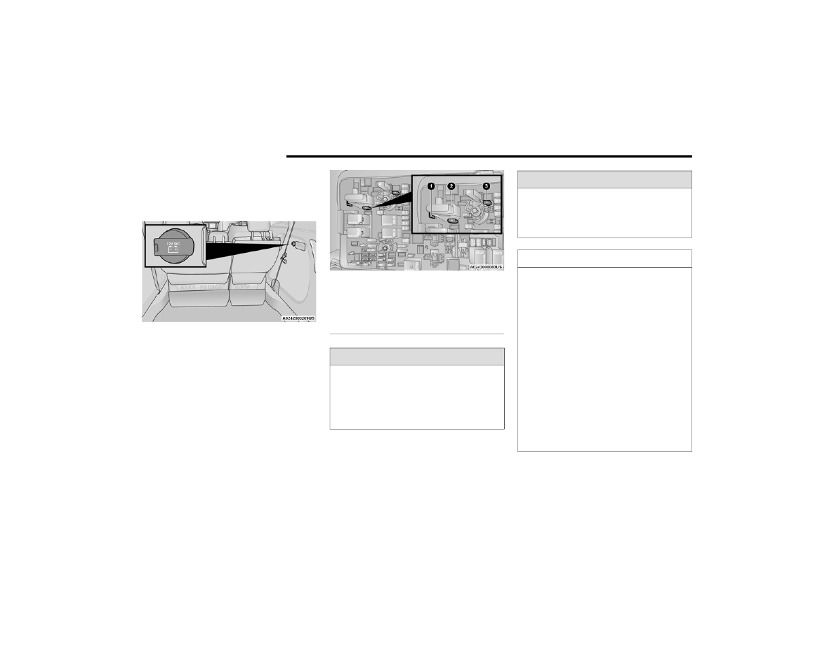
In addition to the front power outlet, there is also a 

power outlet located in the rear cargo area.
The rear power outlet is located in the right rear 

cargo area.

Rear Power Outlet

NOTE:

The instrument panel power outlet can be changed 

to battery powered at all times by switching the 

power outlet fuse in the Power Distribution Center 

panel from fuse location F95A to F95B.

Power Outlet Fuse Locations

1 — F95A (Ignition)/F95B (Battery) 

Front Power Outlet 10A
2 — F85 Cigar Lighter 20A
3 — F60 RR Cargo Power Outlet 20A

WARNING!

To avoid serious injury or death:

Only devices designed for use in this type of 

outlet should be inserted into any 12 Volt 

outlet.

Do not touch with wet hands.

Close the lid when not in use and while driving 

the vehicle.

If this outlet is mishandled, it may cause an 

electric shock and failure.

CAUTION!

Many accessories that can be plugged in draw 

power from the vehicle's battery, even when 

not in use (i.e., cellular phones, etc.). Eventu

-

ally, if plugged in long enough, the vehicle's 

battery will discharge sufficiently to degrade 

battery life and/or prevent the engine from 

starting.

Accessories that draw higher power (i.e., 

coolers, vacuum cleaners, lights, etc.) will 

degrade the battery even more quickly. Only use 

these intermittently and with greater caution.

After the use of high power draw accessories, 

or long periods of the vehicle not being started 

(with accessories still plugged in), the vehicle 

must be driven a sufficient length of time to 

allow the generator to recharge the vehicle's 

battery.

WARNING!

GETTING TO KNOW YOUR VEHICLE

91

P

OWER

 I

NVERTER

 — I

F

 E

QUIPPED


There is a 115 Volt, 150 Watt Power Inverter outlet 

located on the right side of the vehicle, before the 

third row of seats to convert DC current to AC 

current. The Power Inverter can power cellular 

phones, electronics and other low power devices 

requiring up to 150 Watts. Certain video game 

consoles will exceed this power limit, as will most 

power tools.

Power Inverter

The Power Inverter turns on when the device is 

plugged in, and the ignition is in ON/RUN position. 

It turns off when the device is unplugged or the 

ignition is no longer in ON/RUN position.
The Power Inverter is designed with built-in overload 

protection. If the power rating of 

150 Watts is exceeded, the Power Inverter shuts 

down. Once the electrical device has been removed 

from the Power Inverter, it resets. To avoid 

overloading the circuit, check the power ratings on 

electrical devices prior to using the Power Inverter.

W

IRELESS

 C

HARGING

 P

AD

 — 

I

F

 E

QUIPPED

Wireless Charging Pad Location

Your vehicle may be equipped with a 15W 3A Qi 

wireless charging pad located inside of the storage 

area below the climate controls. This charging pad 

is designed to wirelessly charge your Qi enabled 

mobile phone. Qi is a standard that allows wireless 

charging of your mobile phone.
Your mobile phone must be designed for Qi 

wireless charging. If the phone is not equipped 

with Qi wireless charging functionality, an 

aftermarket sleeve or a specialized back plate can 

be purchased from your mobile phone provider or 

a local electronics retailer. Please see your 

phone’s owner’s manual for further information.

WARNING!

To avoid serious injury or death:

Do not insert any objects into the receptacles.

Do not touch with wet hands.

Close the lid when not in use.

If this outlet is mishandled, it may cause an 

electric shock and failure.

2

92

GETTING TO KNOW YOUR VEHICLE


The wireless charging pad is equipped with an 

anti-slip mat to hold your mobile phone in place, 

and an LED indicator light.
LED Indicator Status:

No Light: Charging pad is idle or searching for a 

device.

Blue Light: Device is detected and is charging.

Red Light/Flashing: Internal error or foreign 

object is detected.

NOTE:

All vehicle doors must be closed for the wireless 

charging pad to operate.

Using a phone case may interfere with wireless 

charging.

WINDOWS

P

OWER

 W

INDOWS

The window switches on the driver’s door trim 

panel control all of the door windows.

Driver’s Power Window Controls

The driver may lock out the rear power windows by 

pushing the bar control just below the power 

window controls.

Window Lockout Switch

The window switches will operate only when the 

ignition is in the ACC or ON/RUN position and 

during power accessory delay.

NOTE:

Power Window controls will also remain active for 

up to 10 minutes after the ignition has been 

placed in the OFF position, depending upon the 

accessory delay setting. Opening a front door will 

cancel this feature.
There is a single control on the front passenger’s 

door trim panel which operates the passenger door 

window and a set of controls that lock and unlock 

all doors. The controls will operate only when the 

ignition is in the ACC or ON/RUN position and 

during power accessory delay.

CAUTION!

The key fob should not be placed on the 

charging pad or within 6 inches (15 cm) of it. 

Doing so can cause excessive heat buildup and 

damage to the fob. Placing the fob in close 

proximity of the charging pad blocks the fob from 

being detected by the vehicle and prevents the 

vehicle from starting.

GETTING TO KNOW YOUR VEHICLE

93

Sliding Side Door Power Window Control — 

If Equipped
Second row passengers may open and close the 

sliding door window by a single control on the door 

handle assembly.
The controls will operate only when the ignition 

switch is in the ACC or ON/RUN position and during 

power accessory delay.

NOTE:

The controls will not operate if the driver has acti

-

vated the Power Window Lockout.

Sliding Door Power Window Control (Left Side Shown)

NOTE:

The sliding door windows do not fully open, 

stopping several inches above the window sill.

A

UTOMATIC

 W

INDOW

 F

EATURES

Auto-Down Feature
The driver and front passenger door power window 

switches have an Auto-Down feature. Push the 

window switch down to the second detent, release, 

and the window will go down automatically.
To stop the window from going all the way down 

during the Auto-Down operation, pull up or push 

down on the switch briefly.
Auto-Up Feature With Anti-Pinch Protection
Lift the window switch up to the second detent, 

and release; the window will go up automatically.
To stop the window from going all the way up 

during the Auto-Up operation, push down on the 

switch briefly.
To close the window part way, lift the window 

switch briefly and release it when you want the 

window to stop.
If the window runs into any obstacle during 

auto-closure, it will reverse direction and then go 

back down. Remove the obstacle and use the 

window switch again to close the window.

NOTE:

Any impact due to rough road conditions may 

trigger the auto-reverse function unexpectedly 

during auto-closure. If this happens, pull the switch 

lightly and hold to close the window manually.

R

ESET

 A

UTO

-U

P

Should the Auto-Up feature stop working, the 

window may need to be reset. To reset Auto-Up:
1. Pull the window control up to close the 

window completely and continue to hold the 

control up for an additional two seconds after 

the window is closed.

2. Push the window switch down firmly to open 

the window completely and continue to hold 

the switch down for an additional two seconds 

after the window is fully open.

WARNING!

There is no anti-pinch protection when the 

window is almost closed. To avoid personal 

injury be sure to clear your arms, hands, fingers 

and all objects from the window path before 

closing.

2

94

GETTING TO KNOW YOUR VEHICLE


(Continued)

W

IND

 B

UFFETING

Wind buffeting can be described as the perception 

of pressure on the ears or a helicopter-type sound 

in the ears. Your vehicle may exhibit wind buffeting 

with the windows down, or the sunroof (if 

equipped) in certain open or partially open 

positions. This is a normal occurrence and can be 

minimized. If the buffeting occurs with the rear 

windows open, open the front and rear windows 

together to minimize the buffeting. If the buffeting 

occurs with the sunroof open, adjust the sunroof 

opening to minimize the buffeting or open any 

window.

PANORAMIC SUNROOF — IF EQUIPPED

The Panoramic Sunroof switch is located to the left 

between the sun visors on the overhead console.
The Power Shade switch is located to the right 

between the sun visors on the overhead console.

Panoramic Sunroof And Power Shade Switches

O

PENING

 A

ND

 C

LOSING

 T

HE

 S

UNROOF

Express Open/Close
Push the open switch and release it within one 

second. The sunroof will open automatically from 

any position and stop at the full open position. 

This is called Express Open.
Push the close switch and release it within one 

second and the sunroof will close automatically 

from any position. The sunroof will close fully and 

stop automatically. This is called Express Close.

1 — Sunroof Switch
2 — Power Shade Switch
3 — Vent Button

WARNING!

Never leave children unattended in a vehicle, 

or with access to an unlocked vehicle. Never 

leave the key fob in or near the vehicle, or in a 

location accessible to children. Do not leave 

the Keyless Enter ‘n Go™ Ignition in the ACC or 

ON/RUN position. Occupants, particularly 

unattended children, can become entrapped 

by the power sunroof while operating the 

power sunroof switch. Such entrapment may 

result in serious injury or death.

In a collision, there is a greater risk of being 

thrown from a vehicle with an open sunroof. 

You could also be seriously injured or killed. 

Always fasten your seat belt properly and 

make sure all passengers are also properly 

secured.

Do not allow small children to operate the 

sunroof. Never allow your fingers, other body 

parts, or any object, to project through the 

sunroof opening. Injury may result.

WARNING!

GETTING TO KNOW YOUR VEHICLE

95

NOTE:

During Express Open or Express Close opera

-

tion, any other actuation of the switch will stop 

the sunroof.

If the sunshade is in the closed position when 

the open switch is pushed, the sunshade will 

automatically cycle to the halfway open position 

prior to the sunroof opening.

Manual Open/Close
Push and hold the open switch and the sunroof will 

open to the full open position.
To close the sunroof, push and hold the close 

switch.
Any release of the switch during open or close 

operation will stop the movement and the sunroof 

will remain in a partially open condition until the 

sunroof switch is pushed again.

O

PENING

 A

ND

 C

LOSING

 T

HE

 P

OWER


S

UNSHADE

 — I

F

 E

QUIPPED

The sunshade has two programmed open 

positions: half-open and full-open. When opening 

the sunshade from the closed position, the 

sunshade will always stop at the half-open position 

regardless of express or manual open operation. 

The switch must be actuated again to continue to 

the full-open position.

Express Open/Close
Push the sunshade open switch and release it 

within one second and the sunshade will open to 

the half-open position and stop automatically. 

Push and release the sunshade open switch again 

from the half-open position and the sunshade will 

open to the full-open position and stop 

automatically. This is called Express Open.
Push the sunshade close switch and release it 

within one second and the sunshade will close 

automatically from any position. If the sunroof is 

completely closed, the shade will close fully and 

stop automatically. This is called Express Close.

NOTE:

During Express Open or Express Close opera

-

tion, any movement of the sunshade switch will 

stop the shade.

If the sunroof is open, the shade will close to the 

half-open position. Pushing the shade close 

button again will automatically close both the 

sunroof and shade completely.

Manual Open/Close
Push and hold the sunshade open switch and the 

shade will open to the half-open position and stop 

automatically. Push and hold the sunshade open 

switch again and the shade will open automatically 

to the full-open position.

To close the shade, push and hold the sunshade 

close switch.
Any release of the switch will stop the movement 

and the sunshade will remain in a partially opened 

condition until the switch is pushed again.

P

INCH

 P

ROTECT

 F

EATURE

This feature will detect an obstruction in the 

closing of the sunroof during the Express Close 

operation. If an obstruction in the path of the 

sunroof is detected, the sunroof will automatically 

retract. Remove the obstruction if this occurs.

NOTE:

If three consecutive sunroof close attempts result in 

Pinch Protect reversals, Pinch Protect will disable 

and the sunroof must be closed in Manual Mode.

V

ENTING

 S

UNROOF

Push and release the Vent button within one 

second and the sunroof will open to the vent 

position. This is called Express Vent, and it will 

occur regardless of sunroof position.

NOTE:

If the sunshade is in the closed position when the 

vent switch is pushed, the sunshade will automati

-

cally cycle to the halfway open position prior to the 

sunroof opening to the Vent position.

2

96

GETTING TO KNOW YOUR VEHICLE


I

GNITION

 O

FF

 O

PERATION

The power sunroof switch will remain active for up 

to approximately 10 minutes after the ignition 

switch is placed in the OFF position. Opening either 

front door will cancel this feature.

NOTE:

Ignition off time is programmable through the 

Uconnect system  

Ú

page 188.

S

UNROOF

 M

AINTENANCE

Use only a non-abrasive cleaner and a soft cloth to 

clean the glass panel. Periodically check for and 

clear out any debris that may have collected in the 

tracks.

HOOD    

O

PENING

If applicable, refer to the “Hybrid Supplement” for 

additional information.
The hood release lever (to open the primary latch) 

and safety latch (to open the secondary latch) 

must be released to open the hood.
1. Pull the hood release lever located under the 

driver’s side of the instrument panel.

Hood Release Lever

2. Move to the outside of the front of the vehicle.
3. Push the safety latch release lever toward the 

passenger side of the vehicle. The safety latch 

is located behind the center front edge of the 

hood.

Safety Latch Release Lever Location

4. Remove the support rod from the locking tab 

and insert it into the seat located on the 

underside of the hood.

NOTE:

Before lifting the hood, check that the wiper arms 

are not in motion and not in the lifted position.

While lifting the hood, use both hands.

Vehicle must be at a stop and the gear selector 

must be in PARK.

C

LOSING

If applicable, refer to the “Hybrid Supplement” for 

additional information.
1. Hold up the hood with one hand and with the 

other hand remove the support rod from its 

seat and reinsert it into the locking tab.

2. Lower the hood to approximately 12 inches 

(30 cm) from the engine compartment and 

drop it. Make sure that the hood is completely 

closed.

WARNING!

Be sure the hood is fully latched before driving 

your vehicle. If the hood is not fully latched, it 

could open when the vehicle is in motion and 

block your vision. Failure to follow this warning 

could result in serious injury or death.

GETTING TO KNOW YOUR VEHICLE

97

LIFTGATE

T

O

 U

NLOCK

/O

PEN

 T

HE

 L

IFTGATE

The liftgate may be released in several ways:

Key fob

Liftgate Release Handle

Button on overhead console

Push the liftgate button on the key fob twice within 

five seconds to release the liftgate.
The key fob and the overhead console button will 

release the liftgate when the liftgate is locked. The 

outside handle requires the liftgate to be unlocked. 

If the vehicle is equipped with Passive Entry, 

pulling the electronic liftgate release handle will 

unlock and release the liftgate, with a valid Passive 

Entry key fob within 5 ft (1.5 m) of the liftgate.

Electronic Liftgate

NOTE:

When you push the Passive Entry button, either 

only the liftgate will unlock, or all the doors and the 

liftgate will unlock, depending on the selected 

setting in the Uconnect system  

Ú

page 188.

T

O

 L

OCK

/C

LOSE

 T

HE

 L

IFTGATE

To manually close the liftgate, grab the liftgate 

closing handle and pull in a downward motion.
With a valid Passive Entry key fob within 5 ft 

(1.5 m) of the liftgate, push the Passive Entry lock 

button located to the right of the outside handle to 

lock the vehicle.

P

OWER

 L

IFTGATE

 — I

F

 E

QUIPPED

The power liftgate may be opened or closed in 

several ways:

Overhead console liftgate button

Key fob

Outside handle (opens liftgate only)

Rear Interior Power Liftgate button 

(when liftgate is open)

Hands-Free Liftgate (if equipped) — 

opens liftgate only

CAUTION!

To prevent possible damage, do not slam the 

hood to close it. Lower hood to approximately 

12 inches (30 cm) and drop the hood to close. 

Make sure hood is fully closed for both latches. 

Never drive vehicle unless hood is fully closed, 

with both latches engaged.

1 — Electronic Liftgate Release Handle
2 — Passive Entry Lock Button

WARNING!

Driving with the liftgate open can allow 

poisonous exhaust gases into your vehicle. 

You and your passengers could be injured by 

these fumes. Keep the liftgate closed when 

you are operating the vehicle.

If you are required to drive with the liftgate 

open, make sure that all windows are closed, 

and the climate control blower switch is set at 

high speed. Do not use the recirculation 

mode.

2

98

GETTING TO KNOW YOUR VEHICLE


Using the above ways to open or close the liftgate:

When the liftgate is fully closed, the liftgate will 

open

When the liftgate is fully open, the liftgate will 

close

When the liftgate is moving, the liftgate will 

reverse

Push the Power Liftgate button on the overhead 

console to open or close the liftgate.
Push the liftgate button on the key fob twice within 

five seconds to open or close the liftgate.

Overhead Console Power Switches

The key fob and the overhead console button will 

operate the liftgate when the liftgate is locked. The 

outside handle requires the liftgate to be unlocked. 

If the vehicle is equipped with Passive Entry, 

pressing the touch pad on the outside handle or 

Hands-Free Liftgate foot activation (if equipped) 

will unlock and open the liftgate, with a valid 

Passive Entry key fob within 5 ft (1.5 m) of the 

liftgate handle.

NOTE:

To open the liftgate, the Hands-Free Liftgate 

foot activation (if equipped) requires a valid 

Passive Entry key fob within 5 ft (1.5 m) of the 

door handle.

When you push the Passive Entry button, either 

only the liftgate will unlock, or all the doors and 

the liftgate will unlock, depending on the 

selected setting in the Uconnect system.

Tones are sounded and the turn signals are 

flashed with liftgate movements. These alerts 

can be turned on or off in Uconnect Settings  

Ú

page 188.

To Close The Liftgate
The liftgate can also be closed using the Rear 

Interior Power Liftgate button (if equipped), located 

in the upper left trim in the liftgate opening.

Rear Interior Power Liftgate Button

To Lock The Vehicle
With a valid Passive Entry key fob within 5 ft 

(1.5 m) of the liftgate, pushing the Passive Entry 

lock button located to the right of the outside 

handle will lock the vehicle.

1 — Liftgate
2 — Left Sliding Door
3 — Sliding Door Power Off
4 — Right Sliding Door

GETTING TO KNOW YOUR VEHICLE

99

H

ANDS

-F

REE

 L

IFTGATE

 — I

F

 E

QUIPPED

Hands-Free Liftgate Activation Zone

To open the liftgate using hands-free activation, 

use a straight in and out kicking motion under the 

vehicle activation zone in the general location 

below the liftgate door handle. Do not move your 

foot sideways or in a sweeping motion or the 

sensors may not detect the motion.

Vehicles Equipped With A Trailer Tow Package

NOTE:

If your vehicle is equipped with the Trailer Tow 

Package, the hands-free activation zone(s) for the 

Power Liftgate will be located on the left and right 

side of the receiver. Use a straight kicking motion 

under either activation zone to open the 

Hands-Free Liftgate.

Hands-Free Liftgate Trailer Tow Activation Zones

When a valid kicking motion is completed, the 

liftgate will chime, the hazard lights will flash and 

the liftgate will open after approximately one 

second. This assumes all options are enabled in 

the Uconnect system.

NOTE:

To open the Hands-Free Liftgate requires a valid 

Passive Entry key fob within 5 ft (1.5 m) of the door 

handle. If a valid Passive Entry key fob is not within 

5 ft (1.5 m), the liftgate will not respond to any 

kicks.

NOTE:

The Hands-Free Liftgate will only operate when 

the transmission is in PARK.

If anything obstructs the Hands-Free Liftgate 

while it is opening or closing, the liftgate will 

automatically reverse to the closed position, 

provided it meets sufficient resistance.

There are pinch sensors attached to the side of 

the liftgate opening. Light pressure anywhere 

along these strips will cause the liftgate to 

return to the open position.

CAUTION!

The Hands-Free Liftgate feature may be turned 

on or off in Uconnect Settings. The Hands-Free 

Liftgate feature should be turned off during 

jacking, tire changing, and vehicle service  

Ú

page 188.

2

100

GETTING TO KNOW YOUR VEHICLE


If the power liftgate encounters multiple 

obstructions within the same cycle, the system 

will automatically stop. If this occurs, the liftgate 

must be operated manually.

The power liftgate will release, but not power 

open, in temperatures below −12°F (−24°C). 

Be sure to remove any buildup of snow or ice 

from the liftgate before opening the liftgate.

If the liftgate is left open for an extended period 

of time, the liftgate may need to be closed 

manually to reset power liftgate functionality.

The Hands-Free Liftgate only works to open the 

liftgate.

Gas props support the liftgate in the open position. 

However, because the gas pressure drops with 

temperature, it may be necessary to assist the 

props when opening the liftgate in cold weather.

NOTE:

Allow the power system to open the liftgate. 

Manually pushing or pulling the liftgate may 

activate the liftgate obstacle detection feature and 

stop the power operation or reverse its direction.

C

ARGO

 A

REA

 F

EATURES


Cargo Area Storage

When the third row seats are not in the stowed 

position, there is a large area for cargo storage.

Rear Cargo Area

NOTE:

With all rear seats stowed or removed, 4 x 8 ft 

(1.2 x 2.4 m) sheets of building material will fit on 

the vehicle floor with the liftgate closed. The front 

seats must be moved slightly forward of the 

rearmost position.

Stow ‘n Vac Integrated Vacuum —

If Equipped 

Your vehicle may be equipped with an integrated 

vacuum system. This vacuum is for in-vehicle use 

only and should only be used on dry materials and 

on in-vehicle surfaces. It is located in the rear trim 

panel behind the sliding door on the driver’s side of 

the vehicle.

WARNING!

Driving with the liftgate open can allow 

poisonous exhaust gases into your vehicle. 

You and your passengers could be injured by 

these fumes. Keep the liftgate closed when 

you are operating the vehicle.

If you are required to drive with the liftgate 

open, make sure that all windows are closed, 

and the climate control blower switch is set at 

high speed. Do not use the recirculation 

mode.

WARNING!

During power operation, personal injury or cargo 

damage may occur. Ensure the liftgate travel 

path is clear. Make sure the liftgate is closed 

and latched before driving away.

GETTING TO KNOW YOUR VEHICLE

101

(Continued)

IMPORTANT SAFETY INSTRUCTIONS
Read all instructions before using. When using 

your vacuum, basic precautions should be 

followed, including the following:

WARNING!

Never leave children alone in a vehicle, or

with access to an unlocked vehicle. Allowing 

children to be in a vehicle unattended is 

dangerous for a number of reasons. A child or 

others could be seriously or fatally injured. 

Children should be warned not to touch the 

parking brake, brake pedal or the gear 

selector.

Do not leave the key fob in or near the vehicle, 

or in a location accessible to children, and do 

not leave the Keyless Enter ‘n Go™ Ignition in 

either the ACC position, or engine running 

(ON), unless you are using the vacuum 

system. Be aware a child could operate power 

windows, other controls, or move the vehicle 

when the vacuum system is in use. ALWAYS 

push ignition button to place ignition in the 

OFF position when finished using the vacuum 

system.

WARNING!

To reduce the risk of fire, serious injury or death:

 Do not use vacuum while vehicle is 

in motion or while driving.

Do not vacuum wet surfaces or any liquids.

Do not use to vacuum up anything outside of 

the vehicle.

 Do not vacuum any flammable 

liquids, such as gasoline, or use 

around explosive vapors. Vapors 

from flammable liquids may form an 

explosive mixture with air and can be ignited 

by heat, sparks, or flames. Vapors may travel 

to a source of ignition and explode. 

Do not vacuum anything that is burning or 

smoking, such as cigarettes, matches, or hot 

ashes/embers.

Do not allow to be used as a toy. Close atten

-

tion is necessary when used by or near chil

-

dren.

Do not leave the vacuum running while unat

-

tended.

Use only as described in this manual. Use only 

attachments provided with your vehicle.

Do not put any object into openings. Do not 

use with any opening blocked; keep free of 

dust, lint, hair, and anything that may reduce 

air flow.

Do not vacuum toxic material such as chlorine 

bleach, ammonia, drain cleaner, etc.

Do not vacuum hard or sharp objects such as 

glass, nails, screws, coins, etc.

Keep hair, loose clothing, fingers, and all parts 

of body away from openings and moving parts.

Only use with filter in place. Periodically check 

that the filter is in place and in good condition.

WARNING!

This equipment incorporates parts such as 

switches, motors, or the like that tend to 

produce arcs or sparks that can cause an 

explosion. When using your vacuum near 

gasoline-dispensing equipment or service 

stations, park vehicle at least 20 ft (6 m) away 

from the exterior enclosure of any dispensing 

pump. The vacuum is mounted more than 

18 inches (45 cm) above ground level in your 

vehicle.

WARNING!

2

102

GETTING TO KNOW YOUR VEHICLE


The vacuum will operate in two modes:

Ignition in the ACC position: Engine remains off, 

and vacuum usage is limited to 10 minutes.

Ignition in the START position: Engine is running, 

and vacuum usage is unlimited until the 

vehicle’s battery level falls below 60%.

NOTE:

The vacuum will not operate when the ignition is in 

the OFF position, or in the ON/RUN position with 

the engine off. For more information on ignition 

positions, see  

Ú

page 18.

1. Before Using Vacuum:

Accessory (ACC) Mode Operation - For up to 

10 minutes of operation
Always apply the parking brake, shift the trans

-

mission into PARK, and push ignition button to 

place ignition in Accessory (ACC) mode. The 

engine will not be running in this mode. Do not 

leave the key fob in or near the vehicle, or in a 

location accessible to children.

NOTE:

The vacuum system will run for 10 minutes off 

battery power and then the vacuum will shut down. 

A low battery indication light (LOW PWR) located 

below the vacuum nozzle storage location will 

come on one minute before the vacuum shuts 

down.

Engine Running (START) Operation - For more 

than 10 minutes of operation

Position vehicle outdoors and fully open all 

side windows.

Always apply the parking brake, shift the 

transmission into PARK, and leave engine 

running.

2. Unclip the vacuum nozzle and pull to extend 

vacuum hose from the storage location.

NOTE:

The hose can reach every corner of the vehicle 

floor.
3. Install desired attachment if needed.

Front Storage Compartments

WARNING!

Carbon monoxide (CO) in exhaust gases can 

cause serious injury or death. Follow these 

precautions to prevent carbon monoxide 

poisoning:

Do not inhale exhaust gases.

Do not start or run an engine in a closed 

garage or confined area. Always position 

vehicle outdoors and fully open all side 

windows before using vacuum system with the 

engine running.

Guard against carbon monoxide with proper 

maintenance. Have the exhaust system 

inspected every time the vehicle is raised. 

Have any abnormal conditions repaired 

promptly.

1 — Vacuum Nozzle Storage Location
2 — Attachment Compartment

GETTING TO KNOW YOUR VEHICLE

103

(Continued)

(Continued)

NOTE:

To access crevice or upholstery attachments, open 

the front Attachment Compartment. 

Crevice Tool — Able to reach into tight 

spaces including the seat latches located in 

the floor.

Upholstery Tool — Use to agitate dirt and 

debris from carpets and seats. This tool can 

also be used to pick up pet hair.

Hose Extension — Use to add another 12 ft 

(3.6 m) of usable length to the vacuum 

hose. Hose extension is provided in a bag 

attached to a grocery hook behind the third 

row seat on the driver’s side.

4. Push the vacuum on/off button   located 

under the vacuum nozzle storage location. 

Use vacuum as needed.

NOTE:

When the vacuum is ON, the LED indicator 

on the on/off button will illuminate.

When the vacuum is OFF, the LED indicator 

will also be off.

After nine minutes of operation in ACC 

mode (engine not running), the Low Power 

Indicator Light (LOW PWR) will illuminate.

Power Buttons

1 — Low Power Indicator Light
2 — On/Off Button

WARNING!

For in vehicle use ONLY. To reduce the risk of 

fire, serious injury or death:

 Do not use vacuum while vehicle is 

in motion or while driving.

Do not vacuum wet surfaces or any liquids.

Do not use to vacuum up anything outside of 

the vehicle.

 Do not vacuum any flammable 

liquids, such as gasoline, or use 

around explosive vapors. Vapors 

from flammable liquids may form an 

explosive mixture with air and can be ignited 

by heat, sparks, or flames. Vapors may travel 

to a source of ignition and explode.

Do not vacuum anything that is burning or 

smoking, such as cigarettes, matches, or hot 

ashes/embers.

Do not allow to be used as a toy. Close atten

-

tion is necessary when used by or near chil

-

dren.

Do not leave the vacuum running while unat

-

tended.

Use only as described in this manual. Use only 

attachments provided with your vehicle.

Do not put any object into openings. Do not 

use with any opening blocked; keep free of 

dust, lint, hair, and anything that may reduce 

air flow.

WARNING!

2

104

GETTING TO KNOW YOUR VEHICLE


5. When finished, push power button to turn 

vacuum off and store vacuum hose and any 

attachments.

6. Before exiting the vehicle:

If the ignition is in the ACC position, push 

the START/STOP ignition button to place 

ignition in the OFF position, remove key fob 

from the vehicle, and lock the vehicle.

If the engine is running, raise all of the 

windows, push the START/STOP ignition 

button to place ignition in the OFF position, 

remove key fob from the vehicle, close all of 

the doors and the liftgate and lock the 

vehicle.

Vacuum Troubleshooting

DO NOT use with any opening blocked. If an 

object becomes lodged in the hose, attempt to 

fully extend the hose in a straight line while the 

vacuum motor is running. If this does not 

dislodge the object, turn the vacuum OFF and 

remove the hose from the vehicle using the 

subsequent removal instructions. If the filter is 

clogged, follow the emptying debris bin proce

-

dure and lightly tap the filter on the collection 

bin to remove any collected debris from the 

filter. Both the bin and the filter can be rinsed 

with water if needed. To avoid mold and stale 

odors, allow both to dry completely before rein

-

stalling in your vehicle. If the filter has tears, 

holes or other damage and needs to be 

replaced, please contact an authorized dealer.

If there are any other issues with your vacuum, 

contact an authorized dealer. Your vacuum has 

no user serviceable parts.

Debris Bin
The debris bin is located behind the access panel 

behind the third row seat on the driver’s side.
To Empty
1. Push power button to turn vacuum OFF.
2. Open the access panel by pulling the finger 

grip towards you and then pull downward.

Vacuum System Access Panel

Do not vacuum toxic material such as chlorine 

bleach, ammonia, drain cleaner, etc.

Do not vacuum hard or sharp objects such as 

glass, nails, screws, coins, etc.

Keep hair, loose clothing, fingers, and all parts 

of body away from openings and moving parts.

Only use with filter in place. Periodically check 

that the filter is in place and in good condition.

WARNING!

This equipment incorporates parts such as 

switches, motors, or the like that tend to 

produce arcs or sparks that can cause an 

explosion. When using your vacuum near 

gasoline-dispensing equipment or service 

stations, park vehicle at least 20 ft (6 m) away 

from the exterior enclosure of any dispensing 

pump. The vacuum is mounted more than 

18 inches (45 cm) above ground level in your 

vehicle.

WARNING!

GETTING TO KNOW YOUR VEHICLE

105

3. Twist the release knob counterclockwise and 

pull the bin towards you.

Debris Bin Release Knob

4. Remove the filter and dump the debris in a 

trash can. Lightly tap the filter on the collection 

bin to remove loose debris from the filter. If the 

filter is clogged from extended use, have the 

filter replaced by an authorized dealer.

5. Reverse the procedure to reinstall.

NOTE:

The debris bin must be fully installed and locked 

for the vacuum to function properly.

Hose Access Port
The hose access port is located behind the access 

panel behind the third row seat on the driver’s 

side.
To Remove Vacuum Hose For Cleaning
1. Open the access panel.

Vacuum System Access Panel

2. Open the small access panel on the upper 

right side, and unclip the hose from the hose 

access port by pushing the yellow vacuum 

hose release lever with right thumb and lifting 

the hose with index finger.

Vacuum Hose Release Lever

3. Return to vacuum nozzle storage location 

located behind the sliding door.

4. Grab the vacuum nozzle and gently pull the 

hose out through vacuum nozzle storage 

location.

5. Shake the hose to remove any objects stuck in 

the hose. Take care not to perforate the hose 

while attempting to dislodge any objects.

6. Reverse the procedure to reinstall and clip the 

hose into place.

2


Content      ..     4      5      6      7     ..